- -$10.00


Electrical System & Wiring Diagrams
General Electrical Information
Vehicle Wiring Harnesses
Engine, Chassis & Cab Connections
Electrical Power Distribution Network
Ignition System
Steering Column Switch Assembly
Thermostarter & Engine Preheating System
Central Interconnecting Unit
Battery Charging System
Engine Starting System
Engine Preheating Circuits
Speedometer & Instrument Panel
Optical Indicators & Warning Lights
Exterior Lighting System
Direction Indicators & Signal Lights
Fog, Reversing & Brake Lights
Windscreen Wipers & Washers
Auxiliary Electrical Services
Fuse, Relay & Connection Reference
Electrical Troubleshooting & Diagnostic Reference
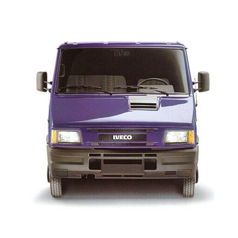
When working on aging heavy-duty commercial vans like the 35-12, 49-12, or 59-12, electrical faults rarely announce themselves cleanly. A flickering warning light or erratic exterior lighting usually points to a deeper routing problem rather than a simple blown bulb. Because the 1996 update bridged the gap between earlier Sofim engines and the emerging 2.8L TDI generation, the electrical architecture is unique to this specific era.
A common issue technicians encounter is tracing phantom power losses through the Central Interconnecting Unit. This vintage of commercial vehicle heavily utilizes physical relay and diode holders instead of modern digital CAN networks. Consequently, running an Iveco TurboDaily InterCooler parasitic draw diagnosis requires precise internal wiring diagrams. This 84-page OEM reference maps out both the positive and the negative power networks exactly as they were assembled at the factory.
During the winter months, these high-performance intercooled diesels rely entirely on the Electronic Module for Thermostarter Control. When a delivery truck refuses to fire up on a cold morning, mechanics often blindly replace the glow plugs or swap out the battery. In real-world repair scenarios, however, the fault frequently lies within the control module's command circuitry.
This technical document features a dedicated troubleshooting chart specifically for the Thermostarter. By utilizing the factory electrical schematics, you can perform accurate voltage drop testing directly at the module itself and trace the pre-heating signal straight back to the ignition switch, preventing unnecessary and expensive parts swapping.
One frequent mistake during reassembly after major cab bodywork or rust repair is pinching a harness within the roof panels or doors. These late-90s variants feature highly specific interconnection points that distribute power from the cabin to the chassis.
The workshop reference provides explicit layouts for the Roof-Door-Cab cable connections as well as the Engine-Chassis-Bonnet harness points. Instead of ripping out the entire dashboard to find a broken wire feeding the windscreen wipers, you can isolate the exact connection socket detailed in the diagrams.
Whether you are fixing a dead speedometer, calibrating the optical indicators, or chasing a short in the reversing lamps, having the accurate wiring layout is mandatory. The guide breaks down the complex steering wheel switch assembly and details the exact routing for main beam, dipped headlights, and fog-reversing-stop lights, ensuring your electrical repairs are permanent.
Stop waiting on mailed paper manuals while a commercial vehicle eats up valuable shop space. Secure your diagnostic data immediately using Apple Pay, Google Pay, PayPal, or any standard Credit Card.
The moment your transaction clears, a direct download link for the EWD manual PDF is fired to your email and securely stored in your personal account dashboard. Your file access is valid for 10 days (with a 10-download limit), allowing you to easily transfer the 84-page document to your diagnostic Toughbook, office PC, or mobile device. Operating behind a strict shop firewall? We guarantee backup file delivery via a secure Dropbox link upon request. If you need a quick visual guide on retrieving your purchase, watch our quick access video tutorial here. Get the wiring diagrams download now and start fixing trucks with absolute precision.
What is the best way to trace a parasitic drain through the Central Interconnecting Unit?
Start by accessing the specific Central Interconnecting Unit chapter. It provides the exact layout of the internal wiring diagram, alongside fuse identification and the positions of all relay and diode-holders. This allows you to isolate the positive network draws circuit by circuit directly at the connection sockets.
Does this factory schematic cover the pre-heating system on the late-90s TDI variants?
Yes. The document includes detailed wiring charts and a dedicated troubleshooting table for the Electronic Module for Thermostarter Control, allowing you to accurately diagnose cold-start and pre-heating failures.
Can this document help identify faults in the steering wheel switch assembly?
Absolutely. The reference includes isolated circuit diagrams specifically for the steering wheel switch assembly, which manages everything from the optical indicators to the windscreen washers and wipers.
Where can I find the pinout reference guide for the main dashboard interconnects?
Navigate to the "Vehicle Cables" section. It thoroughly details the connection points for the Cables for Cab - Roof Panels - Door, providing exact socket layouts for diagnosing dash and cabin electrical shorts.