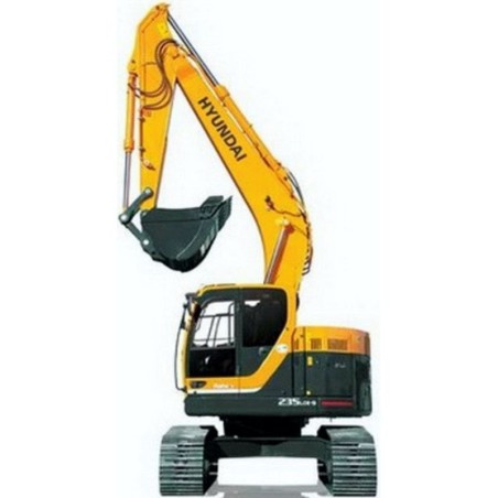
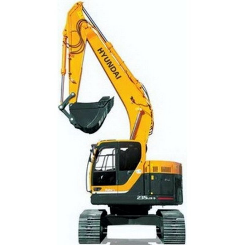
Hyundai Crawler Excavator R235LCR-9 - Service Manual - Operators - Wiring Diagrams
Digital technical documentation with sections on FOREWORD, SECTION 1, Group 1 Safety Hints. Review the complete contents below for the systems and procedures covered.
Manual contents
- SERVICE MANUAL
- - FOREWORD
- - CONTENTS
- - SECTION 1
- - GENERAL
- - Group 1 Safety Hints
- - Group 2 Specifications
- - SECTION 2
- - STRUCTURE
- - Group 1 Pump Device
- - Group 2 Main Control Valve
- - Group 3 Swing Device
- - Group 4 Travel Device
- - Group 5 RCV Lever
- - Group 6 RCV Pedal
- - SECTION 3
- - HYDRAULIC SYSTEM
- - Group 1 Hydraulic Circuit
- - Group 2 Main Circuit
- - Group 3 Pilot Circuit
- - Group 4 Single Operation
- - Group 5 Combined Operation
- - SECTION 4
- - ELECTRICAL SYSTEM
- - Group 1 Component Location
- - Group 2 Electrical Circuit
- - Group 3 Electrical Component Specification
- - Group 4 Connectors
- - SECTION 5
- - MECHATROMICS SYSTEM
- - Group 1 Outline
- - Group 2 Mode selection System
- - Group 3 Travel Speed Control System
- - Group 4 Automatic Warming Up Function
- - Group 5 Engine Overheat Prevention Function
- - Group 6 Automatic Warming Up Function
- - Group 7 Self-Diagnostic System
- - Group 8 Engine Control System
- - Group 9 Monitoring System
- - SECTION 6
- - TROUBLESHOOTING
- - Group 1 Before troubleshooting
- - Group 2 Hydraulic and Mechanical System
- - Group 3 Electrical System
- - Group 4 Mechatronics System
- - SECTION 7
- - MAINTENANCE STANDARD
- - Group 1 Operational Performance Test
- - Group 2 Major Components
- - Group 3 Track and Work Equipment
- - SECTION 8
- - DISASSEMBLY AND ASSEMBLY
- - Group 1 Precaution
- - Group 2 Tightening Torque
- - Group 3 Pump Device
- - Group 4 Main Control Valve
- - Group 5 Swing Device
- - Group 6 Travel Device
- - Group 7 RCV Lever
- - Group 8 Turning Joint
- - Group 9 Boom, Arm and Bucket Cylinder
- - Group 10 Undercarriage
- - Group 11 Work Equipment
- - SECTION 9
- - COMPONENT MOUNTING TORQUE
- - Group 1 Introduction guide
- - Group 2 Engine system
- - Group 3 Electric system
- - Group 4 Hydraulic system
- - Group 5 Undercarriage
- - Group 6 Structure
- - Group 7 Work equipment
- ENGINE SERVICE MANUAL
- - About the Manual i-2
- - General lnformation i-2
- - Accelerator Options FB-3
- - Disadvantages FB-3
- - Driver Activation/Deactivation FB-3
- - Feature Description FB-3
- - Interaction with other Features and Parameters FB-3
- - Visual Aids FB-3
- - Acronyms and Abbreviations i-13
- - General lnformation i-13
- - Additional Service Literature L-1
- - General information L-1
- - Air Cleaner Restriction 4-1
- - Maintenance Check 4-1
- - Air Compressor 4-2
- - Maintenance Check 4-2
- - Air Compressor Air Pressure Rises Slowly TS-3
- - Air Compressor Discharge Lines 7-1
- - General lnformation 7-1
- - Maintenance Check 7-1
- - Air Intake Piping 4-3
- - Maintenance Check 4-3
- - Air Intake System V-5
- - Specifications V-5
- - Air Tanks and Reservoirs 3-2
- - Drain 3-2
- - Alternate Droop FB-4
- - Disadvantages FB-5
- - Driver Activation/Deactivation FB-5
- - Feature Description FB-4
- - Interaction with other Features and Parameters FB-5
- - Visual Aids FB-5
- - Alternator A-1
- - Finishing Steps A-6
- - General lnformation A-1
- - Initial Check A-1
- - lnstall A-5
- - Preparatory Steps A-3
- - Remove A-4
- - Test ' A-2
- - Automatic Boost Power FB-7
- - Disadvantages FB-7
- - Driver Activation/Deactivation FB-7
- - Feature Description FB-7
- - Interaction with other Features and Parameters FB-7
- - Visual Aids FB-7
- - California Emission Control System Warranty, Off-Highway W-6
- - Capscrew Markings and Torque Values V-18
- - Capscrew Markings and Torque Values - Metric V-18
- - Capscrew Markings and Torque Values - US Customary V-18
- - General lnformation V-18
- - Charge-Air Cooler 4-2
- - Maintenance Check 4-2
- - Charge-Air Cooler A-6
- - Clean A-6
- - Inspect for Reuse A-7
- - Leak Test A-7
- - Pressure Differential Test A-9
- - Temperature Differential Test A-8
- - Charge-Air Piping 4-2
- - Maintenance Check 4-2
- - Cold Weather Starting 1-4
- - General lnformation 1-4
- - Using Starting Aids 1-5
- - Component Manufacturers' Addresses M-1
- - Air Compressors M-1
- - Air Cylinders M-1
- - Air Heaters M-1
- - Air Starting Motors M-1
- - Alternators M-1
- - Auxiliary Brakes M-1
- - Belts M-1
- - Catalytic Converters M-1
- - Coolant Level Switches M-1
- - Clutches M-1
- - Coolant Heaters M-2
- - Drive Plates M-2
- - Electric Starting Motors M-2
- - Electronic Switches M-2
- - Engine Protection Controls M-2
- - Fan Clutches , M-2
- - Fans M-2
- - Fault Lamps M-2
- - Filters M-2
- - Flexplates M-2
- - Fuel Coolers M-2
- - Fuel Pumps M-2
- - Fuel Warmers M-2
- - Gauges M-3
- - Governors M-3
- - Heat Sleeves M-3
- - Hydraulic and Power Steering Pumps M-3
- - In-Line Connectors M-3
- - Oil Heaters M-3
- - Prelubrication Systems M-3
- - Radiators M-3
- - Throttle Assemblies M-3
- - Torque Converters M-3
- - Coolant Contamination TS-11
- - Coolant Level 4-4
- - Maintenance Check ; 4-4
- - Coolant Loss - External TS-12
- - Coolant Recommendations and Specifications V-13
- - Cooling System Sealing Additives V-14
- - Cooling System Soluble Oils V-15
- - Fully Formulated Coolant/Antifreeze V-13
- - Coolant Temperature Above Normal - Gradual Overheat , TS-13
- - Coolant Temperature Above Normal - Sudden Overheat TS-15
- - Coolant Thermostat A-1 o
- - Clean and Inspect for Reuse A-12
- - Finishing Steps A-14
- - General Information A-1 o
- - lnstall A-14
- - Preparatory Steps A-11
- - Remove A-12
- - Fan, Cooling 4-3
- - Inspect for Reuse 4-3
- - Cooling Fan Belt Tensioner 6-1
- - Maintenance Check 6-1
- - Cooling Fan Belt Tensioner A-15
- - Maintenance Check A-15
- - Cooling System 5-1
- - Drain : 5-2
- - Fill 5-5
- - Flush 5-3
- - General lnformation 5-1
- - Maintenance Check 5-2
- - Cooling System 7-2
- - Drain 7-3
- - Fill 7-6
- - Flush 7-4
- - General lnformation 7-2
- - Cooling System V-4
- - Specifications V-4
- - Crankcase Breather Tube 3-2
- - Maintenance Check 3-2
- - Cummins Customized Parts Catalog L-3
- - General lnformation L-3
- - Ordering the Customized Parts Catalog L-3
- - Ordering by Telephone L-3
- - Ordering On-Line L-3
- - Cummins/Fleetguard® Filter Specifications V-8
- - General Information V-8
- - Daily Maintenance Procedures - Overview 3-1
- - Engine Operation Report 3-1
- - General lnformation 3-1
- - Unusual Engine Noise 3-1
- - Distributors - International S-31
- - Locations S-31
- - Distributors and Branches S-4
- - Australia S-22
- - Canada S-19
- - New Zealand S-26
- - United States S-4
- - Division and Regional Offices S-2
- - Locations , 8-2
- - Drive aelt Tension V-16
- - Tension Chart V-16
- - Drive Belt, Cooling Fan A-16
- - Inspect for Reuse A-16
- - Install A-17
- - Remove A-16
- - Drive Belts 3-3
- - Maintenance Check 3-3
- - Poly-Vee Belt 3-3
- - Cogged Belt 3-4
- - Electrical System V-7
- - Batteries (Specific Gravity) V-7
- - Specifications V-7
- - Electromagnetic Interference (EMI) 1-B
- - General lnformation 1-8
- - System EMI Radiation Levels 1-8
- - System EMI Susceptibility 1-8
- - Emergency and Technical Service S-1
- - General Information S-1
- - Engine Acceleration or Response Poor TS-18
- - Engine Diagrams E-4
- - Engine Views E-4
- - Engine Difficult-Start or Will Not Start (Exhaust Smoke) TS-20
- - Engine Difficult-Start or Will Not Start (No Exhaust Smoke) TS-22
- - Engine Identification E-1
- - Air Compressor E-3
- - Cummins® Engine Nomenclature E-2
- - ECM Dataplate E•3
- - Engine Dataplate E-1
- - Fuel Injection Pump Dataplate E-2
- - Engine Noise Excessive - Combustion Knocks , TS-26
- - Engine Operating Range 1-8
- - General Information 1-8
- - Engine Power Output Low TS-27
- - Engine Runs Rough at ldle TS-29
- - Engine Runs Rough or Misfires TS-30
- - Engine Shutdown 1 •8
- - General lnlormation 1-8
- - Engine Shuts Off Unexpectedly or Dies During Deceleration TS-32
- - Engine Speed Surges at Low or High ldle TS-33
- - Engine Speed Surges in PTO or Cruise Control TS-36
- - Engine Speed Surges Under Load or in Operating Range TS-34
- - Engine Starts But Will Not Keep Running TS-37
- - Engine Will Not Crank or Cranks Slowly (Air Starter) TS-39
- - Engine Will Not Crank or Cranks Slowly (Electric Starter) TS-41
- - Engine Will Not Reach Rated Speed (RPM) TS-42
- - Exhaust System V-6
- - Specifications V-6
- - Fan Control FB-1
- - Disadvantages FB-1
- - Driver Activation/Deactivation FB-1
- - Feature Description FB-1
- - Interaction with other Features and Parameters FB-1
- - Visual Aids FB-1
- - Fan Hub, Belt Driven 6-2
- - Maintenance Check 6-2
- - Fan Spacer and Pulley A-17
- - Inspect for Reuse A-17
- - lnstall : A-18
- - Preparatory Steps A-17
- - Remove A-17
- - Flow Diagram, Air Intake System D-10
- - Flow Diagram D-10
- - Flow Diagram, Compressed Air System : D-14
- - Flow Diagram D-14
- - Flow Diagram, Cooling System D-9
- - Flow Diagram 0-9
- - Flow Diagram, Exhaust System D-11
- - Flow Diagram D-11
- - Without EGR D-11
- - With EGA 0-12
- - Marine Applications D-13
- - Flow Diagram, Fuel System D-2
- - Flow Diag,ram D-2
- - With Electric Lift Pump D-3
- - Flow Diagram, Lubricating Oil System D-4
- - Flow Diagram D-4
- - Fuel Consumption Excessive TS-46
- - Fuel Consumption Rate Logger FB-8
- - Disadvantages FB-8
- - Driver Activation/Deactivation FB-8
- - Feature Description FB-8
- - Interaction with other Features and Parameters FB-8
- - Visual Aids FB-8
- - Fuel Filter (Spin•On Type) 5-6
- - lnstall , 5-6
- - Prime 5-7
- - Remove 5-6
- - Fuel in the Lubricating Oil TS-49
- - Fuel Recommendations and Specifications V-9
- - Fuel Recommendations V-9
- - Fuel System V-2
- - Preparatory Steps V-2
- - Fuel-Water Separator 3-2
- - Drain 3-2
- - Canister Type 3-2
- - Spin-on Type 3-3
- - General Cleaning Instructions i-9
- - Abrasive Pads and Abrasive Paper i-9
- - Definition of Clean i-9
- - Gasket Surfaces i-10
- - Plastic Bead Cleaning i-11
- - Solvent and Acid Cleaning i-10
- - Steam Cleaning i-11
- - General Repair Instructions i-6
- - General Information i-6
- - Welding on a Vehicle with an Electronic Controlled Fuel System i-6
- - General Safety Instructions i-6
- - Important Safety Notice i-6
- - General Engine V-1
- - Specifications V-1
- - Hot Shutdown Monitor FB-6
- - Disadvantages FB-7
- - Driver Activation/Deactivation FB-7
- - Feature Description FB-6
- - Interaction with other Features and Parameters FB-7
- - Visual Aids , FB-7
- - How-Use the Manual i-3
- - General lnlormation i-3
- - Idle Shutdown FB-2
- - Disadvantages FB-2
- - Driver Activation/Deactivation FB-2
- - Feature Description FB-2
- - Interaction with other Features and Par,meters FB-2
- - Visual Aids FB-2
- - Illustrations i-5
- - General Information i-5
- - Intermediate Speed Control (ISC) , FB-3
- - Disadvantages FB-4
- - Driver Activation/Deactivation FB-4
- - Feature Description FB-3
- - Interaction with other Features and Parameters FB-4
- - Visual Aids FB-4
- - Lubricating Oil and Filters 5-7
- - Drain 5-7
- - Fill 5-9
- - lnstall 5-6
- - Remove : 5-6
- - Lubricating Oil Consumption Excessive TS-53
- - Lubricating Oil Contaminated , TS-54
- - Lubricating Oil Level 3-3
- - Maintenance Check 3-3
- - Lubricating Oil Loss TS-55
- - Lubricating Oil Pressure High TS-57
- - Lubricating Oil Pressure Low TS-56
- - Lubricating Oil Recommendations and Specifications V-10
- - General lnformation V-10
- - New Engine Break-in Oils V-12
- - Lubricating Oil Sludge in the Crankcase Excessive TS-60
- - Lubricating Oit System V-3
- - Specifications V-3
- - Maintenance Guidelines• Overview 2-1
- - General Information 2-1
- - Maintenance Procedures - Overview 4-1
- - General lnformation 4-1
- - Maintenance Procedures - Overview 5-1
- - General lnformation 5-1
- - Maintenance Procedures• Overview 6-1
- - General lnformation 6-1
- - Maintenance Procedures Overview 7-1
- - General Information 7-1
- - Maintenance Procedures - Overview 8-1
- - General Information 6-1
- - Maintenance Record Form 2-4
- - Maintenance Data 2-4
- - Maintenance Schedule 2-3
- - General Information 2-3
- - Oil Drain lntervals 2-3
- - Multiple Unit Synchronization FB-5
- - Disadvantages FB-6
- - Driver Activation/Deactivation FB-6
- - Feature Description FB-5
- - Interaction with other Features and Parameters FB-6
- - Visual Aids FB-6
- - Normal Starting Procedure , 1-2
- - General Information 1-2
- - Jump Starting 1-4
- - All Engines lnternationallndustrial (Off-Highway) , W-4
- - All Engines United States and Canada Industrial (Off-Highway) W-1
- - Operating Instructions - Overview H
- - General Information 1-1
- - Operating the Engine : 1-5
- - Ambient Temperature 1-6
- ---32°C 132--25°FJ 1:6
- - -32--54°C [-25--65°FJ 1•6
- - Cold Weather 1-6
- - Normal 1-5
- - Winterfronts and Shutters 1-7
- - Overhead Set 8-1
- - Adjust 8-3
- - Finishing Steps 8-7
- - lnstall 6-5
- - Preparatory Steps 8-1
- - Remove 8-1
- - Problem Solving 8-1
- - General lnformation $-1
- - Radiator Hoses 4-3
- - Maintenance Check 4-3
- - Regional Offices - International $-27
- - Locations $-27
- - Routine Service and Parts 8-1
- - General Information S-1
- - Sealants V-17
- - General lnformation V-17
- - Service Literature Ordering Location L-2
- - Contact lnformation L-2
- - Starting Motor A-18
- - Clean and Inspect for Reuse A-20
- - lnstall A-21
- - Cummins Branded Starters A•22
- - Non-Cummins Branded Starters A-22
- - Measure A-21
- - Remove A-19
- - Rotation Check A-18
- - Starting Procedure After Extended Shutdown or Oil Change 1-5
- - General Information 1-5
- - Switchable (Alternate) Torque FB-5
- - Disadvantages FB-5
- - Driver Activation/Deactivation FB-5
- - Feature Description FB-5
- - Interaction with other Features and Parameters FB-5
- - Visual Aids FB-5
- - Symbols i-4
- - General Information i-4
- - System Diagrams - Overview D-1
- - General lnformation D-1
- - To the Owner and Operator i-1
- - General Information i-1
- - Tool Requirements 2-2
- - General Information 2-2
- - Troubleshooting Procedures and Techniques TS-1
- - General lnformation TS-1
- - Troubleshooting Symptoms Charts TS-2
- - General Information TS-2
- - Turbocharger Leaks Engine Oil or Fuel TS-64
- - Vibration Damper, Rubber 7-7
- - Inspect 7-7
- - Vibration Damper, Viscous c 7-7
- - Inspect 7-7
- - Water-in-Fuel Sensor FB-1
- - Disadvantages FB-2
- - Driver Activation/Deactivation FB-2
- - Feature Description FB-1
- - Interaction with other Features and Parameters FB-2
- - Visual Aids FB-2
- OPERATORS MANUAL
- - FOREWORD
- - SECTION 1
- - SAFETY HINT
- - Group 1 Before operating the machine
- - Group 2 During operating the machine
- - Group 3 During maintenance
- - Group 4 Parking
- - SECTION 2
- - SPECIFICATIONS
- - Group 1 Major components
- - Group 2 Specifications
- - Group 3 Working range
- - Group 4 Weight
- - Group 5 Lifting capacities
- - Group 6 Bucket selection guide
- - Group 7 Undercarriage
- - Group 8 Specification for major components
- - Group 9 Recommended oils
- - SECTION 3
- - CONTROL DEVICE
- - Group 1 Cab device
- - Group 2 Cluster
- - Group 3 Switches
- - Group 4 Levers and pedals
- - Group 5 Air conditioner and heater
- - Group 6 Others
- - SECTION 4
- - OPERATION
- - Group 1 Suggestion for new machine
- - Group 2 Check before starting the engine
- - Group 3 Starting and stop the engine
- - Group 4 Mode selection system
- - Group 5 Operation of the working device
- - Group 6 Traveling of the machine
- - Group 7 Efficient working method
- - Group 8 Operation in the special work sites
- - Group 9 Normal operation of excavator
- - Group 10 Attachment lowering Pattern
- - Group 11 Storage
- - Group 12 RCV lever operating pattern
- - Group 13 Switching Hydraulic attachment circuit
- - SECTION 5
- - TRANSPORTATION
- - Group 1 Preparation for transportation
- - Group 2 Dimension and weight
- - Group 3 Loading the machine
- - Group 4 Fixing the machine
- - Group 5 Loading and unloading by crane
- - SECTION 6
- - MAINTENANCE
- - Group 1 Instructions
- - Group 2 Tightening torque
- - Group 3 Specification of fuel, coolant and lubricants
- - Group 4 Maintenance check list
- - Group 5 Maintenance chart
- - Group 6 Service instruction
- - Group 7 Electrical system
- - Group 8 Air conditioner and heater
- - SECTION 7
- - TROUBLESHOOTING GUIDE
- - Group 1 Engine
- - Group 2 Electrical system
- - Group 3 Others
- - SECTION 8
- - HYDRAULIC BREAKER
- - Group 1 Selecting hydraulic breaker
- - Group 2 Circuit configuration
- - Group 3 Maintenance
- - Group 4 Precaution while operating the breaker
- - Group 5 Quick clamp
- - INDEX