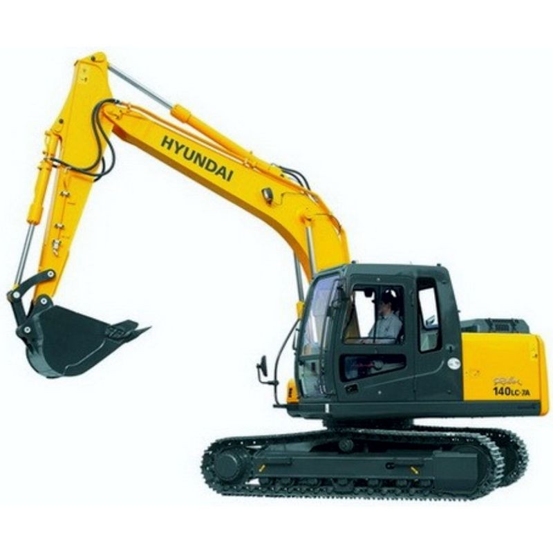
Hyundai Crawler Excavator R140LC-7A - Service Manual - Operators - Wiring Diagrams
Digital technical documentation with sections on FOREWORD, SECTION 1, Group 1 Safety Hints. Review the complete contents below for the systems and procedures covered.
Manual contents
- SERVICE MANUAL
- - FOREWORD
- - CONTENTS
- - SECTION 1
- - GENERAL
- - Group 1 Safety Hints
- - Group 2 Specifications
- - SECTION 2
- - STRUCTURE
- - Group 1 Pump Device
- - Group 2 Main Control Valve
- - Group 3 Swing Device
- - Group 4 Travel Device
- - Group 5 RCV Lever
- - Group 6 RCV Pedal
- - SECTION 3
- - HYDRAULIC SYSTEM
- - Group 1 Hydraulic Circuit
- - Group 2 Main Circuit
- - Group 3 Pilot Circuit
- - Group 4 Single Operation
- - Group 5 Combined Operation
- - SECTION 4
- - ELECTRICAL SYSTEM
- - Group 1 Component Location
- - Group 2 Electrical Circuit
- - Group 3 Electrical Component Specification
- - Group 4 Connectors
- - SECTION 5
- - MECHATROMICS SYSTEM
- - Group 1 Outline
- - Group 2 Mode selection System
- - Group 3 Travel Speed Control System
- - Group 4 Automatic Warming Up Function
- - Group 5 Engine Overheat Prevention Function
- - Group 6 Automatic Warming Up Function
- - Group 7 Self-Diagnostic System
- - Group 8 Engine Control System
- - Group 9 Monitoring System
- - SECTION 6
- - TROUBLESHOOTING
- - Group 1 Before troubleshooting
- - Group 2 Hydraulic and Mechanical System
- - Group 3 Electrical System
- - Group 4 Mechatronics System
- - SECTION 7
- - MAINTENANCE STANDARD
- - Group 1 Operational Performance Test
- - Group 2 Major Components
- - Group 3 Track and Work Equipment
- - SECTION 8
- - DISASSEMBLY AND ASSEMBLY
- - Group 1 Precaution
- - Group 2 Tightening Torque
- - Group 3 Pump Device
- - Group 4 Main Control Valve
- - Group 5 Swing Device
- - Group 6 Travel Device
- - Group 7 RCV Lever
- - Group 8 Turning Joint
- - Group 9 Boom, Arm and Bucket Cylinder
- - Group 10 Undercarriage
- - Group 11 Work Equipment
- - SECTION 9
- - COMPONENT MOUNTING TORQUE
- - Group 1 Introduction guide
- - Group 2 Engine system
- - Group 3 Electric system
- - Group 4 Hydraulic system
- - Group 5 Undercarriage
- - Group 6 Structure
- - Group 7 Work equipment
- ENGINE SERVICE MANUAL
- - Outline drawings
- - System flow
- - General Engine serial number location
- - Main specifications
- - Tips on disassembling and reassembling
- - Service data
- - Maintenance service data
- - List of tightening torque
- - Basic and special tools Special tools
- - Overhaul instructions
- - Determining overhaul timing
- - Testing compression pressure
- - Disassembling and inspecting cylinder head and valve mechanism
- - Disassembling engine main parts
- - Disassembling and inspecting flywheel
- - Disassembling and inspecting gear case, timing gear and camshaft
- - Disassembling and inspection crankcase, crankshaft and piston
- - Inspecting and repairing cylinder head and valve mechanism
- - Inspecting and repairing engine main Inspecting and repairing flywheel
- - parts Inspecting and repairing timing gears and camshaft
- - Inspecting and repairing piston, connecting rod, crankshaft and crankcase
- - Reassembling piston, connecting rod, crankshaft and crankcase
- - Reassembling engine main parts
- - Reassembling timing gear and camshaft
- - Reassembling flywheel
- - Reassembling cylinder head and valve mechanism
- - Removing fuel system
- - Fuel system Assembling fuel system
- - Installing fuel system
- - Removing and inspecting lubrication system
- - Lubrication system Disassembling, inspecting and reassembling lubrication system
- - Installing lubrication system
- - Removing cooling system
- - Cooling system Disassembling, inspecting and reassembling cooling system
- - Installing cooling system
- - Removing inlet and exhaust system
- - Inlet and exhaust systems Disassembling, inspecting and reassembling inlet and exhaust
- - Installing inlet and exhaust system
- - Removing electrical system
- - Electrical system Disassembling, inspecting and reassembling electrical system
- - Installing electrical system
- - Adjustment, break-in operation and
- - Adjusting engine
- - Break-in operation
- - performance test
- - Performance test (JIS standard)
- - Electronic troubleshooting
- - Programming parameters
- - System configuration parameters
- - Troubleshooting Troubleshooting without a diagnostic code
- - Troubleshooting with a diagnostic code
- - Troubleshooting with an event code
- - Diagnostic functional tests
- OPERATORS MANUAL
- - FOREWORD
- - SECTION 1
- - SAFETY HINT
- - Group 1 Before operating the machine
- - Group 2 During operating the machine
- - Group 3 During maintenance
- - Group 4 Parking
- - SECTION 2
- - SPECIFICATIONS
- - Group 1 Major components
- - Group 2 Specifications
- - Group 3 Working range
- - Group 4 Weight
- - Group 5 Lifting capacities
- - Group 6 Bucket selection guide
- - Group 7 Undercarriage
- - Group 8 Specification for major components
- - Group 9 Recommended oils
- - SECTION 3
- - CONTROL DEVICE
- - Group 1 Cab device
- - Group 2 Cluster
- - Group 3 Switches
- - Group 4 Levers and pedals
- - Group 5 Air conditioner and heater
- - Group 6 Others
- - SECTION 4
- - OPERATION
- - Group 1 Suggestion for new machine
- - Group 2 Check before starting the engine
- - Group 3 Starting and stop the engine
- - Group 4 Mode selection system
- - Group 5 Operation of the working device
- - Group 6 Traveling of the machine
- - Group 7 Efficient working method
- - Group 8 Operation in the special work sites
- - Group 9 Normal operation of excavator
- - Group 10 Attachment lowering Pattern
- - Group 11 Storage
- - Group 12 RCV lever operating pattern
- - Group 13 Switching Hydraulic attachment circuit
- - SECTION 5
- - TRANSPORTATION
- - Group 1 Preparation for transportation
- - Group 2 Dimension and weight
- - Group 3 Loading the machine
- - Group 4 Fixing the machine
- - Group 5 Loading and unloading by crane
- - SECTION 6
- - MAINTENANCE
- - Group 1 Instructions
- - Group 2 Tightening torque
- - Group 3 Specification of fuel, coolant and lubricants
- - Group 4 Maintenance check list
- - Group 5 Maintenance chart
- - Group 6 Service instruction
- - Group 7 Electrical system
- - Group 8 Air conditioner and heater
- - SECTION 7
- - TROUBLESHOOTING GUIDE
- - Group 1 Engine
- - Group 2 Electrical system
- - Group 3 Others
- - SECTION 8
- - HYDRAULIC BREAKER
- - Group 1 Selecting hydraulic breaker
- - Group 2 Circuit configuration
- - Group 3 Maintenance
- - Group 4 Precaution while operating the breaker
- - Group 5 Quick clamp
- - INDEX