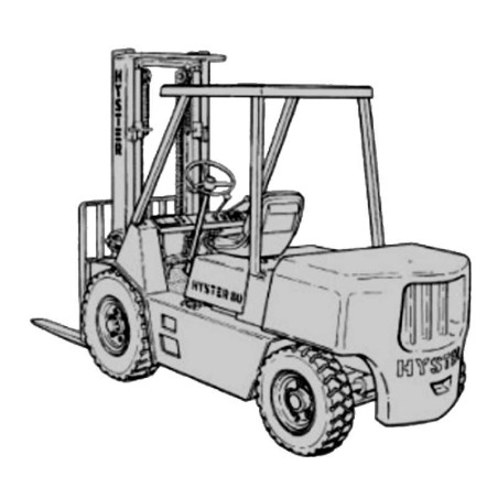
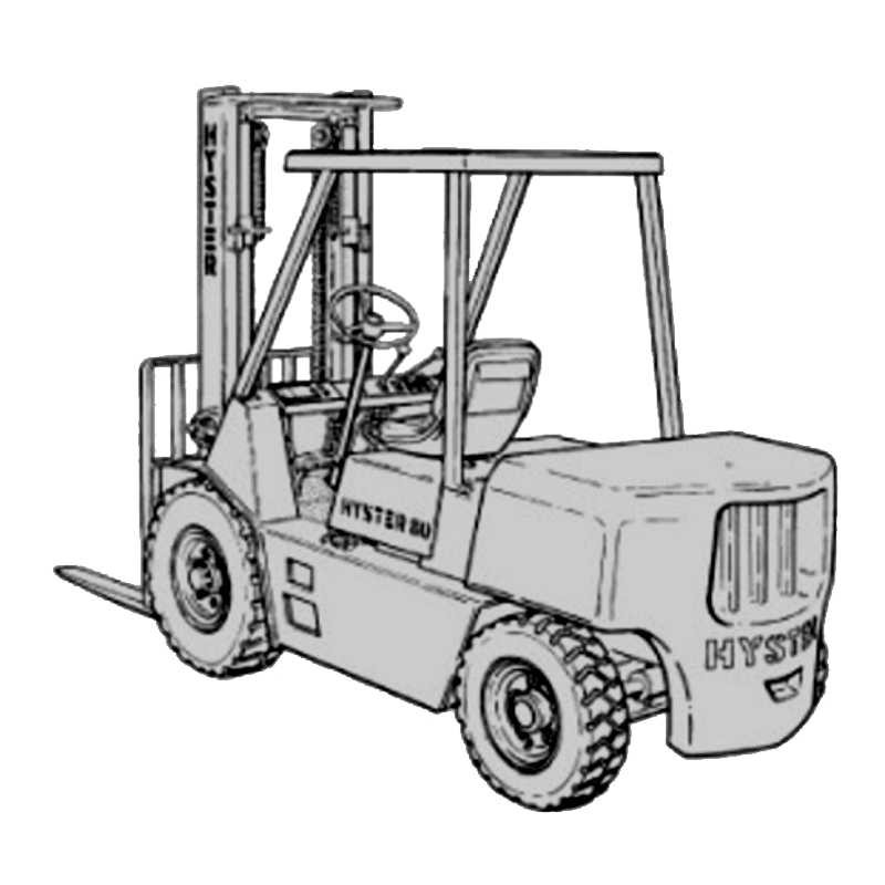
Hyster H135 155XL - Service Repair Manual - Wiring Diagrams
Digital technical documentation with sections on Lift Truck Weights, Capacities, Tire Sizes. Review the complete contents below for the systems and procedures covered.
Manual contents
- 01 GENERAL INFORMATION
- - Lift Truck Weights
- - Capacities
- - Tire Sizes
- - Tire Pressure
- - Electrical System
- - Wheel Nut Torque
- - Engine Specifications -Gasoline/Lpg
- - Hydraulic System
- - Mast Speeds
- - Transmission Oil Pressures
- - Torque Specifications
- 02 GM 4.3 LITRE V–6 AND 5.7 LITRE V–8 ENGINES
- - Gm 4.3 Litre V-6 And 5.7 Litre V-8 Engines
- - Description
- - Engine, Removal And Installation
- - Cylinder Head
- - Removal And Disassembly
- - Cleaning And Inspection
- - Repairs, Valve Guides And Seats
- - Studs For The Rocker Arms
- - Valve Springs
- - Assembly And Installation
- - Cylinder Block, Cleaning And Inspection
- - Piston Bore Prepartion
- - Engine Mounts
- - Lubrication System
- - Oil Pump, Removal And Disassembly
- - Cleaning And Inspection
- - Oil Pump, Assembly And Installation
- - Timing Cover, Timing Sprockets, Camshaft And Cam Followers
- - Timing Cover, Removal
- - Installation
- - Timing Sprockets, Removal
- - Timing Sprockets, Installation
- - Camshaft, Removal
- - Camshaft, Inspection
- - Camshaft, Installation
- - Hydraulic Valve Lifters, Removal
- - Hydraulic Valve Lifters, Disassembly
- - Hydraulic Valve Lifters, Cleaning And Inspection
- - Hydraulic Valve Lifters, Assembly
- - Crankshaft
- - Removal
- - Inspection And Repair
- - How To Check The Clearance Between The Main Bearings And Their Journals
- - Installation
- - Piston And Connecting Rod Assemblies
- - Connecting Rod Bearings, Replacement
- - Piston And Connecting Rod Assemblies, Removal
- - Disassembly
- - Piston, Cleaning And Inspection
- - Cylinder Bores, Inspection And Repair
- - Piston Rings
- - Assembly
- - Piston And Connecting Rod Assemblies, Installation
- - Flywheel And Flyweel Housing
- - Flywheel Repair For V-6 Engines
- - Flywheel For V-6 Engines, Installation
- - Flywheel Housing, H3.5-5.00xl (H70-110xl)
- - Engine Adapter, H6.00-7.00xl (H135-155xl)
- - Ring Gear Replacement (Flywheel) For V-8 Engines
- - Flywheel For V-8 Engines, Flywheel Housing
- - Coolant Pump
- - Fan Mount
- - Checks And Adjustements
- - Valve Clearance Adjustment
- - Engine Specifications
- - Engine Specifications
- - Engine Data
- - Cylinder Head
- - Hydraulic Valve Lifter
- - Camshaft
- - Pistons
- - Crankshaft
- - Connecting Rods
- - Cooling System
- - Lubrication System
- - Torque Specifications For Capscrews And Bolts
- - Troubleshooting
- 03 GM 4.3 LITRE V-6 ENGINE
- - Gm 4.3 Litre V-6
- - Introduction
- - Description
- - Engine, Removal And Installation
- - Cylinder Head
- - Removal And Disassembly
- - Cleaning And Inspection
- - Repairs, Valve Guides And Seats
- - Repairs, Valves
- - Repairs, Valve Seats
- - Valve Springs
- - Studs For The Rocker Arms (Early Models)
- - Studs For The Rocker Arms (Late Models)
- - Assembly And Installation
- - Cylinder Block, Cleaning And Inspection
- - Piston Bore Preparation
- - Engine Mounts
- - Lubrication System
- - Oil Pump, Removal And Disassembly
- - Cleaning And Inspection
- - Oil Pump, Assembly And Installation
- - Oil Sump, Installation
- - Timing Cover, Timing Sprockets, Camshaft And Valve Lifters
- - Timing Cover, Removal
- - Installation
- - Timing Sprockets, Removal
- - Timing Sprockets, Installation
- - Camshaft, Removal
- - Camshaft, Inspection
- - Camshaft, Installation
- - Balance Shaft, Removal
- - Balance Shaft, Installation
- - Hydraulic Valve Lifters, Removal
- - Hydraulic Valve Lifters, Disassembly
- - Hydraulic Valve Lifters, Cleaning And Inspection
- - Hydraulic Valve Lifters, Assembly
- - Hydraulic Valve Lifters, Installation
- - Crankshaft
- - Removal
- - Inspection And Repair
- - How To Check The Clearance Between The Main Bearings And Their Journals
- - Installation
- - Piston And Connecting Rod Assemblies
- - Connecting Rod Bearings, Replacement
- - Piston And Connecting Rod Assemblies, Removal
- - Disassembly
- - Piston, Cleaning And Inspection
- - Cylinder Bores, Inspection And Repair
- - Piston Rings
- - Assembly
- - Piston And Connecting Rod Assemblies, Installation
- - Flywheel And Flywheel Housing
- - Flywheel Repairs
- - Flywheel, Installation
- - Flywheel Housing
- - Engine Adapter
- - Coolant Pump
- - Thermostat
- - Fan Mount, Early Models
- - Fan Mount Assembly, Late Models
- - Drive Belt, Installation
- - Checks And Adjustments
- - Valve Clearance Adjustment, Early Models
- - Valve Clearance Adjustment, New Models
- - Check The Compression
- - Engine Specifications
- - Engine Data
- - Engine Data
- - Cylinder Head
- - Hydraulic Valve Lifter
- - Camshaft
- - Pistons
- - Crankshaft
- - Connecting Rods
- - Connecting Rods
- - Balance Shaft
- - Cooling System
- - Lubrication System
- - Torque Specifications
- - Troubleshooting
- 04 PERKINS 4.236 AND PERKINS 4.2482 DIESEL ENGINES
- - Introduction
- - General
- - Description
- - Engine Serial Number Codes
- - Removal And Installation
- - Engine
- - Cylinder Head
- - Removal
- - Installation
- - Cylinder Head Repairs
- - Oil Pump
- - Removal
- - Disassembly
- - Inspection
- - Assembly
- - Installation
- - Relief Valve
- - Timing Gear Case And Timing Gears
- - Removal
- - Installation
- - Pistons And Connecting Rods
- - Removal
- - Disassembly
- - Inspection
- - Assembly
- - Installation
- - Crankshaft And Main Bearings
- - Removal
- - Inspection
- - Assembly
- - Camshaft And Cam Followers
- - Removal
- - Inspection
- - Assembly
- - Flywheel And Flywheel Housing
- - Removal
- - Repairs
- - Installation
- - Steering Pump Drive
- - Removal
- - Installation
- - Pcv Valve
- - Fuel System
- - Fuel Pump
- - Removal
- - Disassembly
- - Assembly
- - Installation
- - Fuel Injection Pump
- - Removal
- - Repairs
- - Installation
- - Fuel Injectors
- - Removal
- - Repairs
- - Installation
- - Cold Start Aid
- - Description
- - Removal
- - Installation
- - Cooling System
- - Thermostat
- - Removal
- - Inspection
- - Installation
- - Water Pump
- - Removal
- - Disassembly
- - Assembly
- - Installation
- - Checks And Adjustments
- - Checking The Injectors
- - Repairs
- - Installation
- - Removing Air From The Fuel System
- - Checking The Timing Marks
- - Method A
- - Method B
- - Checking The Timing Angle Of The Fuel Injection Pump With The Special Tool
- - Valve Clearance Adjustment
- - Adjusting The Throttle Linkage
- - Troubleshooting
- - Specifications
- - Torque Specifications
- 05 PERKINS 1004-42 (AR) , 1006-60 (YG) , 1006-60T (YH) DIESEL ENGINES
- - Perkins Diesel Engines, 1004-42 (Ar), 1006-60 (Yg), 1006-60t (Yh)
- - General
- - General Safety Rules
- - Description
- - Engine Serial Number Codes
- - Engine Data
- - 1004-42 (Ar) Engine (Low Governed Speed)
- - 1004-42 (Ar) Engine (High Governed Speed)
- - 1006-60 (Yg) Engine
- - 1006-60 (Yh) Engine
- - Removal And Installation
- - Lifting The Engine
- - Cylinder Head Assembly
- - Valve Cover
- - Removal
- - Installation
- - Rocker Arm Assembly
- - Removal
- - Installation
- - Disassembly
- - Inspection
- - Assembly
- - Valve Clearance Adjustments
- - Four Cylinder Engines
- - Six Cylinder Engines
- - Valve Springs
- - Cylinder Head Assembly
- - Removal
- - Installation
- - Valves And Valve Springs
- - Removal
- - Inspection
- - Installation
- - Valve Guides
- - Inspection
- - Removal
- - Installation
- - Cylinder Head And Valve Seats
- - Inspection
- - Repair
- - Installation Of New Valve Seats
- - Piston And Connecting Rod Assemblies
- - Rod Bearings
- - Removal
- - Installation
- - Piston And Connecting Rod Assembly
- - Service Note
- - Removal
- - Installation
- - Piston Rings
- - Removal
- - Inspection
- - Installation
- - Piston And Connecting Rod
- - Disassembly
- - Inspection
- - How To Select The Correct Replacements
- - Installation
- - Piston Cooling Jets
- - Removal
- - Installation
- - Crankshaft Assembly
- - General
- - Crankshaft Pulley
- - Removal, Engine Ar
- - Removal, Engine Yg And Yh
- - Inspection
- - Installation, Engine Ar
- - Installation, Engine Yg And Yh
- - Rear Oil Seal
- - Replacement
- - Main Bearings
- - Removal
- - Inspection
- - Installation
- - Thrust Washers
- - Check The Axial Movement Of The Crankshaft
- - Removal
- - Installation
- - Crankshaft
- - Removal
- - Inspection
- - Installation
- - Flywheel
- - Removal
- - Ring Gear (Replacement)
- - Installation
- - Flywheel Housing
- - Removal
- - Installation
- - Timing Case And Timing Gears
- - General
- - Timing Case Cover
- - Removal
- - Installation
- - Front Oil Seal
- - Removal
- - Installation
- - Crankshaft Pulley Wear Sleeve
- - Installation
- - Idler Gear And Hub
- - Removal
- - Installation
- - Air Compressor Drive, Bendix
- - Disassembly
- - Compressor Drive, Assembly
- - Gear For The Fuel Injection Pump
- - Removal
- - Installation
- - Camshaft Gear
- - Removal
- - Installation
- - Crankshaft Gear
- - Removal
- - Installation
- - Timing Case
- - Removal
- - Installation
- - Camshaft And Tappets
- - Removal
- - Installation
- - Cylinder Block Assembly
- - Description
- - Cylinder Block
- - Disassembly
- - Inspection
- - Assembly
- - Cylinder Bore (4-Cylinder Engines)
- - Cylinder Bore (6-Cylinder Engines)
- - Inspection
- - To Check The Condition Of A Cylinder Liner
- - Removal
- - Installation (Service Liner)
- - Installation (Partially Finished Liner)
- - Engine Timing
- - General Description
- - How To Set Number 1 Piston To Tdc On The Compression Stroke
- - How To Set Number 1 Piston To Tdc On The Compression Stroke (Alternate Procedure)
- - Check The Valve Timing
- - Check The Timing Of The Fuel Injection Pump
- - Turbocharger, Engine Yh
- - General
- - Removal
- - Installation
- - Clean The Impeller And Compressor Housing
- - Lubrication System
- - General
- - Oil Filter, Replacement
- - Filter Head
- - To Remove And To Install
- - Oil Sump
- - Removal
- - Installation
- - Oil Pump
- - Removal
- - Inspection
- - Installation
- - Relief Valve
- - Removal
- - Disassembly
- - Inspection
- - Assembly
- - Installation
- - Idler Gear Shaft, Replacement
- - Removal
- - Removal, Alternative
- - Installation
- - Installation, Alternative
- - Installation, Alternative For 4-Cylinder Engines Only
- - Fuel System
- - Description
- - Fuel Injection Pump
- - Removal
- - Installation
- - Fuel Injection Pump, Checks And Adjustments
- - Remove Air From The Fuel System
- - Fuel Filter (Replacement)
- - Canister Type
- - Quick Release Canister Type
- - Fuel Injectors
- - Removal
- - Inspection
- - Installation
- - Fuel Pump
- - Removal
- - Disassembly
- - Assembly
- - Installation
- - Test
- - Cooling System
- - General
- - Thermostat
- - Thermostats
- - Remove
- - Install
- - Test
- - Coolant Pump
- - Removal
- - Disassembly
- - Assembly
- - Installation
- - Fan And Fan Drive
- - Removal
- - Installation
- - Oil Cooler (6-Cylinder Engines)
- - Removal
- - Disassembly And Assembly
- - Installation
- - By-Pass Valve, Oil Cooler
- - Electrical Equipment
- - Drive Belts
- - Alternator
- - Removal
- - Installation
- - Starter Motor
- - Removal
- - Installation
- - Cold Start Aid
- - Air Compressor, Engines Yg And Yh
- - General
- - Air Compressor, Removal
- - Air Compressor, Installation
- - Engine Specifications
- - Cylinder Head Assembly
- - Cylinder Head
- - Valve Guides
- - Inlet Valve
- - Exhaust Valves
- - Valve Springs
- - Tappets
- - Rocker Arm Shaft
- - Rocker Arms And Bushings
- - Piston And Connecting Rods
- - Pistons (Engine AR)
- - Pistons (Engine YG and YH)
- - Piston Rings (Engine AR)
- - Piston Rings (Engines YG and YH)
- - Piston Pins
- - Connecting Rods
- - Small End Bushings
- - Connecting Rod,Bearings, Engines AR And YG
- - Connecting Rod,Bearings, Engines YH
- - Piston Cooling Jets
- - Crankshaft Assembly
- - Crankshaft
- - Main Bearings
- - Crankshaft Thrust Washers
- - Crankshaft Heat Treatment
- - Crankshaft Overhaul
- - Timing Case And Drive Assembly
- - Camshaft
- - Camshaft Thrust Washer
- - Camshaft Gear
- - Gear For Fuel Injection Pump
- - Crankshaft Gear
- - Idler Gear And Hub
- - Engine Block Assembly
- - Cylinder Block (Engine AR)
- - Cylinder Bore Specifications (Engine AR)
- - Cylinder Block (Engine YG and YH)
- - Cylinder LIners (Engine YG and YH)
- - Cylinder Liner Specifications (Partially Finished)
- - Turbocharger
- - Lubrication System
- - Oil Pump, Engine AR
- - Oil Pump, Engine YG and YH
- - Idler Gear for Oil Pump
- - Relief Valve
- - Oil Filter
- - Fuel System
- - Lucas Fuel Injection Pump
- - Fuel Injector Codes
- - Fuel Pump, Engine AR
- - Fuel Pump, Engines YG And YH
- - Fuel Filter
- - Cooling System
- - Coolant Pump
- - Thermostat
- - Fan Drive Housing
- - Flywheel And Housing
- - Limits for Flywheel "Run Out" and Alignment (Total Indicator Reading)
- - Electrical Equipment
- - Alternator
- - Starter Motor
- - Cold Start Aid
- - Torque Specifications
- - Special Torque Specifications
- - Special Tools
- - Troubleshooting
- - List Of Possible Causes
- 06 LPG FUEL SYSTEM
- - Introduction
- - General
- - Description And Operation
- - Fuel Tank
- - Fuel Filter And Fuel Valve Unit
- - Vaporizer
- - Carburetor
- - Governor
- - Repairs
- - Lpg Tank
- - Removal
- - Installation
- - Hydrostatic Relief Valve
- - Removal And Installation
- - Filter Unit
- - Replacement Of The Fuel Filter Element
- - Replacement Of The Diaphragm And Fuel Valve
- - Replacement Of The Hoses
- - Vaporizer
- - Removal
- - Vaporizer Disassembly
- - Cleaning
- - Inspection
- - Vaporizer Assembly
- - Installation
- - Carburetor
- - Removal
- - Disassembly
- - Cleaning
- - Assembly
- - Installation
- - Governor
- - Checks And Adjustments
- - Check The Filter Unit
- - Check The Vaporizer
- - Pressure Reducer Valve
- - Vapor Valve
- - Adjust The Carburetor
- - Idle Mixture
- - Idle Speed
- - Power Mixture
- - Adjust The Throttle Linkage
- - Troubleshooting
- 07 WEBER CARBURETOR WITH GOVERNOR
- - Weber Carburetor With Governor
- - General
- - Description
- - Carburetor
- - Governor
- - Operation
- - Carburetor, Float System
- - Carburetor, Idle System
- - Carburetor, Main Metering System
- - Carburetor, Power System
- - Carburetor, Accelerator Pump System
- - Carburetor, Choke System
- - Governor
- - Repairs
- - Carburetor
- - Removal
- - Disassembly
- - Cleaning
- - Assembly
- - Installation
- - Governor
- - Checks And Adjustments
- - General
- - Choke System
- - Electric Choke
- - Idle Mixture Adjustment
- - Idle Speed Adjustment
- - Throttle Linkage Adjustment
- - Troubleshooting
- 08 ELECTRONIC CONTROL MODULE (ECM)
- - Introduction
- - General
- - Description And Operation
- - General
- - Electronic Control Module (Ecm)
- - Diagnostic Connector
- - How The Ecm Begins Operation
- - Electronic Engine Control
- - What The Ecm Does
- - Distributor
- - Ignition Module
- - When The Engine Is Being Started
- - When The Engine Is Running
- - Electronic Control Module (Ecm) With Ignition Module Distributor, Corrections
- - Fuel Control
- - Throttle Body Injection
- - Fuel Injectors
- - Fuel Pressure Regulator
- - Throttle Position Sensor
- - Idle Air Control
- - Gm 4.3l Engine Governor System
- - Gm 3.0l Engine Governor System
- - Vacuum Ports
- - Fuel Pump
- - Ecm Sensors And Controllers
- - Manifold Absolute Pressure (Map)
- - Engine Coolant Temperature (Ect) Sensor
- 09 ELECTRONIC ENGINE CONTROL
- - Introduction
- - General
- - Troubleshooting Procedure
- - How This Section Is Arranged
- - Where Do I Start
- - Visual/Physical Inspection
- - Knowledge/Tools Required
- - Damage From Static Discharge (Static Electricity)
- - Troulbleshooting Information
- - Malfunction Indicator Lamp (Mil)
- - Reading Diagnostic Trouble Codes (Dtc)
- - Clearing Diagnostic Trouble Codes (Dtc)
- - Table 1. Ecm Diagnostic Codes Available
- - Diagnostic Mode
- - Field Service Mode
- - Ecm Learning Ability
- - Table 2. Scan Tool Information
- - On-Board Diagnostic (Obd) System Check
- - Troubleshooting Charts
- - General
- - Tools And Test Equipment
- - Chart A-1 No Malfuntion Indicator Lamp
- - Circuit Description
- - Chart A-2 - No Scan Data, No Dtc12, Malfunction Indicator Lamp On
- - Circuit Description
- - Chart A-3 - The Starter Rotates The Engine, Engine Will Not Run
- - Circuit Description
- - Chart A-4 - Fuel Injector Circuit
- - Circuit Description
- - Chart A-5 - Fuel Pump Relay Circuit
- - Circuit Description
- - Chart A-6 - Fuel System Troubleshooting (1 Of 3)
- - Circuit Description
- - Fuel Pressure Check
- - Chart A-7 - Ingition System Troubleshooting
- - Dtc 14 Engine Coolant Temperature Sensor Circuit (Low Temperature Indicated)
- - CIRCUIT DESCRIPTION
- - Dtc 15 Engine Coolant Temperature Sensor Circuit (High Temperature Indicated)
- - CIRCUIT DESCRIPTION
- - CODE 15 - Engine Coolant Temperature Sensor Circuit (High Temperature Indicated)
- - Dtc 21 Throttle Position Sensor Circuit (Signal Voltage High)
- - CIRCUIT DESCRIPTION
- - CODE 21 - Throttle Position Sensor Circuit (Signal Voltage High)
- - Dtc 22 Throttle Position Sensor Circuit (Signal Voltage Low)
- - CIRCUIT DESCRIPTION
- - Dtc 31 Engine Governor Circuit
- - CIRCUIT DESCRIPTION
- AND MORE....