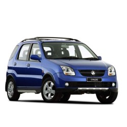
Holden Kalos - Service Manual - Repair Manual
Digital technical documentation with sections on SECTION 00B, Section : 0b General Information, Specifications. Review the complete contents below for the systems and procedures covered.
Manual contents
- SECTION 00B
- Section : 0b General Information
- - Specifications
- - Technical Data
- - Vehicle Dimensions And Weights
- - Standard Bolt Specifications
- - Maintenance And Repair
- - Maintenance And Lubrication
- - Owner Inspections And Services
- - Whle Operating The Vehicle
- - At Each Fuel Fill
- - At Least Monthly
- - At Least Twice A Year
- - Each Time The Oil Is Changed
- - At Least Annually
- - Recommended Fluids And Lubricants
- - General Description And System Operation
- - General Repair Instructions
- - General Description
- - Vehicle And Component Identification
- - Vehicle Lifting Procedures
- SECTION 01A
- Section : 1a - General Engine Information
- - Diagnosis
- - Compression Test
- - Oil Pressure Test
- - Oil Leak Diagnosis
- - Knock Diagnosis
- - Noise Diagnosis
- - General Information
- - Cleanliness And Care
- - On–Engine Service
- SECTION 01B01
- Section : 1b1 - 1.2 Sohc Engine Mechanical
- - Specifications
- - Engine Specifications
- - Fastener Tightening Specifcations
- - Special Tools
- - Special Tools Table
- - Component Locator
- - Cylinder Head
- - Engine Block
- - Manifold & Air Flow System
- - Timing Belt
- - Maintenance And Repair
- - On–Vehicle Service
- - Unit Repair
- - General Description And System Operation
- - Cylinder Head And Valve Train
- - Engine Block
- - Crankshaft
- - Connecting Rod
- - Piston, Piston Ring And Piston Pin
- - Timing Belt And Pulley
- - Engine Mount
- - Exhaust Gas Recirculation Valve
- SECTION 01B02
- Section : 1b2 - 1.4/1.5 Sohc Engine Mechanical
- - Specifications
- - Engine Specifications (1.4 Sohc)
- - Engine Specifications (1.5 Sohc)
- - Fastener Tightening Specifcations
- - Special Tools
- - Special Tools Table
- - Component Locator
- - Upper End
- - Lower End
- - Maintenance And Repair
- - On–Vehicle Service
- - Unit Repair
- - General Description And System Operation
- - Cylinder Head And Gasket
- - Crankahaft
- - Timing Belt
- - Oil Pump
- - Oil Pan
- - Exhaust Manifold
- - Intake Manifold
- - Camshaft
- - Exhaust Gas Recirculation Valve
- SECTION 01D
- Section : 1d - Engine Cooling
- - Specifications
- - Cooling System Specification
- - Fastener Tightening Specifications
- - Special Tools
- - Special Tools Table
- - Diagnosis
- - Thermostat Test
- - Surge Tank Cap Test
- - Cooling Systen Diagnosis
- - Component Locator
- - Radiator/Fan (1.2 Sohc)
- - Radiator/Fan (1.4/1.5 Sohc)
- - Radiator/Fan (1.4 Dohc)
- - Coolant Pump/Thermostat (1.2 Sohc)
- - Coolant Pump/Thermostat (1.4/1.5 Sohc)
- - Coolant Pump/Thermostat (1.4 Dohc)
- - Maintenance And Repair
- - On–Vehicle Service
- - General Description And System Operation
- - General Description
- - Radiator
- - Surge Tank
- - Coolant Pump
- - Thermostat
- - Electric Cooling Fan
- - Coolant Temperature Sensor
- - Engine Block Heater
- SECTION 01E
- Section : 1e - Engine Electrical
- - Specifications
- - Starter Specifications
- - Generator Specifications
- - Battery Specifications
- - Fastener Tightening Specifications
- - Schematic And Routing Diagrams
- - Startimg System
- - Charging System (1.4 Sohc/Dohc/1.5 Sohc)
- - Charging System (1.2 Sohc)
- - Component Locator
- - Staring System (1.2 Sohc)
- - Staring System (1.4 Sohc/Dohc/1.5 Sohc)
- - Charging System (Valeo : Mando)
- - Charging System (1.4 Sohc/Dohc/1.5 Sohc)
- - Diagnosis
- - No Crank
- - Starter Motor Noise
- - Battery Load Test
- - Genrator Output Test
- - Generator System Check
- - Maintenance And Repair
- - On–Vehicle Service
- - Unit Repair
- - General Description And System Operation
- - Battery
- - Ratings
- - Reserve Capacity
- - Cold Cranking Amperage
- - Built – In Hydrometer
- - Charging Procedure
- - Charging Time Required
- - Charging A Completely Discharged Battery (Off The Vehicle)
- - Jump Starting Procedure
- - Generator
- - Charging System
- - Starter
- - Starting System
- SECTION 01F
- Section : 1f - Engine Controls
- - Specifications
- - Engine Data Display Tables
- - Engine Data Display Table Definitions
- - Fastener Tightening Specifications
- - Fuel System Specifications
- - Temperature Vs Resistance
- - Schematic And Routing Diagrams
- - Ecm Wiring Diagram (1.2l Sohc – 1 Of 7)
- - Ecm Wiring Diagram (1.2l Sohc – 2 Of 7)
- - Ecm Wiring Diagram (1.2l Sohc – 3 Of 7)
- - Ecm Wiring Diagram (1.2l Sohc – 4 Of 7)
- - Ecm Wiring Diagram (1.2l Sohc – 5 Of 7)
- - Ecm Wiring Diagram (1.2l Sohc – 6 Of 7)
- - Ecm Wiring Diagram (1.2l Sohc – 7 Of 7)
- - Ecm Wiring Diagram (1.5l Sohc – 1 Of 6)
- - Ecm Wiring Diagram (1.5l Sohc – 2 Of 6)
- - Ecm Wiring Diagram (1.5l Sohc – 3 Of 6)
- - Ecm Wiring Diagram (1.5l Sohc – 4 Of 6)
- - Ecm Wiring Diagram (1.5l Sohc – 5 Of 6)
- - Ecm Wiring Diagram (1.5l Sohc – 6 Of 6)
- - Connector End View
- - Component Locator
- - Component Locator (1.2l Sohc)
- - Component Locator (1.5l Sohc)
- - Diagnosis
- - System Diagnosis
- - Trouble Code Diagnosis (1.2l Sohc)
- - Trouble Code Diagnosis (1.5l Sohc)
- - Symptom Diagnosis
- - Important Preliminary Checks
- - Intermittents
- - Hard Start
- - Surges Or Chuggles
- - Lack Of Power, Sluggishness, Or Sponginess
- - Detonation/Spark Knock
- - Hesitation, Sag, Stumble
- - Cuts Out, Misses
- - Poor Fuel Economy
- - Rough, Unstable, Or Incorrect Ldle, Stalling
- - Excessive Exhaust Emissions Or Odors
- - Dieseling, Run–On
- - Backfire
- - Maintenance And Repair
- - On–Vehicle Service
- - General Description And System Operation
- - Ignition System Operation
- - Electronic Ignition System Ignition Coil
- - Crankshaft Position Sensor
- - Camahaft Position Sensor
- - Idle Air System Operation
- - Fuel Control System Operation
- - Oxygen Sensor (Unleaded Fuel Only)
- - Co Adjuster (Leaded Fuel Only)
- - Evaporative Emission Control System Operation
- - Evaporative Emission Canister
- - Positive Crankcase Ventilation System Operation
- - Engine Coolant Temperature Sensor
- - Throttle Position Sensor
- - Exhaust Gas Recirculation Valve
- - Intake Air Temperature Sensor
- - Idle Air Control Valve
- - Manifold Absolute Pressure Sensor
- - Engine Control Module
- - Fuel Injector
- - Knock Sensor
- - Comprehensive Component Monitor Diagnostic Operation
- SECTION 01G
- Section : 1g - Engine Exhaust
- - Specifications
- - Fastener Tightening Specifications
- - Component Locator
- - Exhaust System
- - Maintenance And Repair
- - On–Vehicle Service
- - General Description And System Operation
- - Exhaust System
- - Muffler
- - Catalytic Converters
- SECTION 02A
- Section : 2a - Suspension Diagnosis
- - Diagnosis
- - General Diagnosis
- - Torque Steer
- - Tapered Roller Bearing
- SECTION 02B
- Section : 2b - Wheel Alignment
- - Specifications
- - Wheel Alignment Specifications
- - Difference Between Left And Right
- - Fastener Tightening Specifications
- - Diagnosis
- - Tire Diagnosis
- - Radial Tire Lead /Pull
- - Vibration Diagnosis
- - Preliminary Inspection
- - Front Toe Adjustment
- - Front Camber And Caster Check
- - Rear Camber Check
- - Rear Toe Check
- - General Description And System Operation
- - Four Wheel Alignment
- - Toe
- - Caster
- - Camber
- - Steering Axis Inclination
- - Included Angle
- - Scrub Radius
- - Setback
- - Turning Angle
- SECTION 02C
- Section : 2c - Front Suspension
- - Specifications
- - General Specifications
- - Fastener Tightening Specifications
- - Special Tools
- - Special Tools Table
- - Diagnosis
- - Strut Dampener
- - Ball Joint And Knuckle
- - Excessive Friction Check
- - Component Locator
- - Front Suspension
- - Maintenance And Repair
- - On–Vehicle Service
- - Unit Repair
- - General Description And System Operation
- - Front Suspension
- SECTION 02D
- Section : 2d - Rear Suspension
- - Specifications
- - Fastener Tightening Specifications
- - Conponent Locator
- - Rear Suspension
- - Special Tools
- - Special Tools Table
- - Diagnosis
- - Excessive Friction Test
- - Maintenance And Repair
- - On–Vehicle Service
- - Unit Repair
- - General Description And System Operation
- - Rear Suspension
- SECTION 02E
- Section : 2e Tires And Wheels
- - Specifications
- - Tire Size And Pressure Specifications
- - Inflation Pressure Conversion Pecifications
- - Fastener Tightening Specifications
- - Diagnosis
- - Wheel Runout
- - Maintenance And Repair
- - On–Vehicle Service
- - Unit Repair
- - General Description And System Operation
- - Tire And Wheel Balancing
- - Replacement Tires
- - Tire Chain Usage
- - All Season Tires
- - Inflation Of Tires
- - Passenger Metric Sized Tires
- - Tire Label
- - Spare Tire
- - Wheels
- SECTION 04A
- Section : 4a Hydraulic Brakes
- - Specifications
- - General Specifcations
- - Fastener Tightening Specifications
- - Component Locator
- - Brake System (Abs)
- - Brake System (Non–Abs)
- - Diagnosis
- - Brake System Testing
- - Brake Hose Inspection
- - Warning Lamp Operation
- - Brake Lamp Warning Circuit Diagnosis
- - Maintenance And Repair
- - On–Vehicle Service
- - General Description And System Operation
- - Hydraulic Fluid
- SECTION 04B
- Section : 4b Master Cylinder
- - Specifications
- - Fastener Tightening Specifications
- - Maintenance And Repair
- - On–Vehicle Service
- - Unit Repair
- - General Description And System Operation
- - Master Cylinder
- - Proportioning Valves
- - Fluid Level Sensor
- SECTION 04C
- Section : 4c Power Booster
- - Specifications
- - Fasrener Tightening Specifications
- - Diagnosis
- - Power Booster Functional
- - Check
- - Maintenance And Repair
- - On–Vehicle Service
- - General Description And System Operation
- - Power Booster
- SECTION 04D
- Section : 4d Front Disc Brakes
- - Specifications
- - Fastener Tightening Specirications
- - Diagnosis
- - Lining Inspection
- - Rotor Inspection
- - Maintenance And Repair
- - On–Vehicle Service
- - Unit Repair
- - General Description And System Operation
- - Disc Brake Caliper Assembly
- SECTION 04E
- Section : 4e Rear Drum Brakes
- - Diagnosis
- - Lining Inspection
- - Drums
- - Maintenance And Repair
- - On–Vehicle Service
- - Unit Repair
- - General Description And System Operation
- - Drum Brakes
- - Specifications
- - Fastener Tightening Specifications
- SECTION 04F
- Section : 4f Antilock Brake System
- - Specifications
- - General Specifications
- - Fastener Tightening Specifications
- - Schematic And Routing Diagrams
- - Abs System Circuit (I)
- - Abs System Circuit (Ii)
- - Electrical Schematic
- - Hecu Harness Connector End View And Pin Layout
- - Hydraulic Diagram
- - Component Locator
- - Abs System
- - Diagnosis
- - Diagnostic Trouble Code And Description
- - Diagnostic Circuit Check
- - No Communication With Hecu
- - Abs Warning Lamp Inoperative/No Dtc Set
- - Abs Warning Lamp On/No Dtc Set
- - Brake Warning Lamp On
- - Brake Warning Lamp Inoperative/No Dtc Set
- - C1101 Battery Voltage Too High
- - C1102 Battery Voltage Too Low
- - C1200 Left Front Wheel Speed Sensor Circuit Open Or Shorted
- - C1201 Left Front Wheel Speed Excessive Variation
- - C1202 Left Front Wheel Speed Sensor No Signal
- - C1203 Right Front Wheel Speed Sensor Circuit Open Or Shorted
- - C1204 Right Front Wheel Speed Excessive Variation
- - C1205 Right Front Wheel Speed Sensor No Signal
- - C1206 Left Rear Wheel Speed Sensor Circuit Open Or Shorted
- - C1207 Left Rear Wheel Speed Excessive Variation
- - C1208 Left Rear Wheel Speed Sensor No Signal
- - C1209 Right Rear Wheel Speed Sensor Circuit Open Or Shorted
- - C1210 Right Rear Wheel Speed Excessive Variation
- - C1211 Right Rear Wheel Speed Sensor No Signal
- - C1604 Hecu Internal Fault
- - C2112 Valve Relay Or Fuse Failure
- - C2402 Pump Motor Failure
- - Maintenance And Repair
- - On–Vehicle Service
- - General Description And System Operation
- - General System Description
- - Basic Knowledge Required
- - Abs System Components
- - Base Braking Mode
- - Antilock Braking Mode – Apply
- - Antilock Braking Mode – Hold
- - Antilock Braking Mode – Release
- - Ddrp (De–Coupled Dynamic Rear Proportioning)
- - Ddrp (De–Coupled Dynamic Rear Proportining) Failure Modes
- - Hecu (Hydraulic Electronic Control Unit)
- - Solenoid Relay
- - Wheel Speed Sensors And Rings
- - Abs Warning Lamp (Amber)
- - Brake Warning Lamp (Red)
- SECTION 04G
- Section : 4g Parking Brake
- - Specifications
- - Fastener Tightening Specifications
- - Maintenance And Repair
- - On–Vehicle Service
- - General Description And System Operation
- - Parking Brake
- SECTION 05A
- Section : 5a Aisin Automatic Transaxle
- - Specifications
- - General Specifications
- - Transaxle Gear Ratio
- - Fluid Capacity
- - Line Pressure Specification
- - Fastener Tightening Specifications
- - Special Tools
- - Special Tools Table
- - Schematic Diagrams
- - Transmission Control Module (1of 4)
- - Transmission Control Module (2 Of 4)
- - Transmission Control Module (3 Of 4)
- - Transmission Control Module (4 Of 4)
- - Shift Mode Diagram
- - Component Locator
- - Shift Select Control
- - Automatic Transaxle Components
- - Bearing And Races Installation Position And Direction
- - Diagnosis
- - Electric Connector View
- - Wiring Harness And Connector Inspection
- - Function Check
- - Unit Inspection
- - On–Vehicle Repair (Matrix Chart)
- - Diagnostic Trouble Code Diagnosis
- - Diagnostic Trouble Code Chart
- - Dtc P0562 System Voltage Low
- - Dtc P0563 System Voltage High
- - Dtc P0604 Internal Transmission Control Module (Tcm) Random Access Memory Error
- - Dtc P0705 Park/Neutral Position Switch Circuit Malfunction
- - Dtc P0712 Transmission Fluid Temperature (Tft) Sensor Circuit Low Input
- - Dtc P0713 Transmission Fluid Temperature (Tft) Sensor Circuit High Input
- - Dtc P0717 Input Shaft Speed (Iss) Sensor Circuit No Signal
- - Dtc P0722 Ouput Shaft Speed (Oss) Sensor Circuit No Signal
- - Dtc P0727 Engine Speed Input Circuit No Signal
- - Dtc P0741 Torque Converter Clutch (Tcc) Citcuit Stuck Off
- - Dtc P0742 Torque Converter Clutch (Tcc) Citcuit Stuck On
- - Dtc P0743 Torque Converter Clutch (Tcc) Electrical
- - Dtc P0748 Pressure Control Solenoid (Pcs) Electrical
- - Dtc P0751 Shift Solenoid 1 (Ss1) Stuck Off
- - Dtc P0753 Shift Solenoid 1 (Ss1) Electrical
- - Dtc P0756 Shift Solenoid 2 (Ss2) Stuck Off
- - Dtc P0758 Shift Solenoid 2 (Ss2) Electrical
- - Dtc P1701 Engine Coolant Temperature (Ect) Signal Error
- - Dtc P1702 Engine Torque Signal Error
- - Dtc P1710 Timing Solenoid (St) Electrical
- - Dtc P1790 Internal Transmission Control Module (Tcm) Random Access Memory (Ram) Checksum Error
- - Dtc P1791 Throttle Position Signal Error
- - Dtc U2105 Can Error
- - Maintenance And Repair
- - On–Vehicle Service
- - Unit Repair
- - General Description And System Operation
- - Transaxle Description
- - Electronical Components
- - Hydraulic Control System
- - Automatic Transaxle System
- SECTION 05B01
- Section : 5b1 Five-Speed Manual Transaxle (D16)
- - Specifications
- - Fastener Tightening Specifications
- - Special Tools
- - Special Tools Table
- - Diagnosis
- - Isolate Noise
- - Symptom Diagnosis
- - Component Locators
- - Gears And Case
- - Bearing Plate
- - Differential Gear
- - Shift Linkage
- - Maintenance And Repair
- - On–Vehicle Service
- - Unit Repair
- - General Description And System Operation
- - Five–Speed Manual Transaxle
- SECTION 05B02
- Section : 5b2 Five-Speed Manual Transaxle (Y4m)
- - Specifications
- - General Specifications
- - Fastener Tightening Specifications
- - Special Tools
- - Special Tools Table
- - Diagnosis
- - General Diagnosis
- - Checking Fluid Level
- - Changing Fluid
- - Checking Transaxle Noise
- - Checking Bearing Noise
- - Component Locators
- - Gear Shift Control
- - Input Shaft And Counter Shaft Gear
- - Gear Shift Fork
- - Differential And Case
- - Maintenance And Repair
- - On–Vehicle Service
- - Unit Repair
- - General Description And System Operation
- - Five–Speed Manual Transaxle
- - Reverse Gear Misshift Preventing Mechanism
- - Differential
- SECTION 05C01
- Section : 5c1 Clutch (Hydraulic Type)
- - Specifications
- - Fastener Tightening Specifications
- - Special Tools
- - Special Tools Table
- - Diagnosis
- - Clutch Operation
- - Component Locator
- - Hydraulic Clutch
- - Clutch Pedal
- - Maintenance And Repair
- - On–Vehicle Service
- - Unit Repair
- - General Description And System Operation
- - Driving Members
- - Driven Members
- - Operating Members
- SECTION 05C02
- Section : 5c2 Clutch (Cable Type)
- - Specifications
- - Fastener Tightening Specifications
- - Special Tools
- - Special Tools Table
- - Diagnosis
- - General Diagnosis
- - Clutch Pedal Operation
- - Clutch Cable Adjustment
- - Clutch Cable
- - Component Locator
- - Clutch Components
- - Maintenance And Repair
- - On–Vehicle Service
- - General Description And System Operation
- - Driving Members
- - Driven Members
- - Operating Members
- SECTION 06A
- Section : 6a Power Steering System
- - Specifications
- - Fastener Tighteming Specifications
- - Special Tools
- - Special Tools Table
- - Component Locator
- - Rack And Pinion Steering Gear
- - Power Steering System
- - Diagnosis
- - Power Steering System Pressure Test
- - Power Steering System Leak Test
- - Maintenance And Repair
- - On–Vehicle Service
- - General Description And System Operation
- - Power Steering System
- SECTION 06B
- Section : 6b Power Steering Pump
- - Specifications
- - General Specifications
- - Fastener Tightening Specifications
- - Special Tools
- - Special Tools Table
- - Diagnosis
- - Power Steering Pump Diagnosis
- - Maintenance And Repair
- - On–Vehicle Service
- - Unit Repair
- - General Description And System Operation
- - Power Steering Pump
- - Seals
- SECTION 06C
- Section : 6c Power Steering Gear
- - Specifications
- - General Specifications
- - Fastener Tightening Specifications
- - Special Tools
- - Special Tools Table
- - Diagnosis
- - Power Rack And Pinion Steering Gear
- - Power Rack And Pinion Steering Gear Bench Testing
- - Maintenance And Repair
- - On–Vehicle Service
- - Unit Repair
- - General Description And System Operation
- - Power Rack And Pinion
- SECTION 06D
- Section : 6d Manual Steering Gear
- - Specifications
- - General Specifications
- - Fastener Tightening Specifications
- - Special Tools
- - Special Tools Table
- - Diagnosis
- - Manual Rack And Pinion Steering Gear
- - Straight–Ahead Check
- - Maintenance And Repair
- - On–Vehicle Service
- - Unit Repair
- - General Description And System Operation
- - Manual Rack And Pinion
- SECTION 06E
- Section : 6e Steering Wheel And Column
- - Specifications
- - Fastener Tightening Specifications
- - Special Tools
- - Special Tools Table
- - Diagnosis
- - Steering Column Diagnosis
- - Maintenance And Repair
- - On–Vehicle Service
- - Unit Repair
- - General Description And System Operation
- - Steering Wheel And Column
- SECTION 07A
- Section : 7a Heating And Ventilation System
- - Specifications
- - Heater Temperature Specifications
- - Fastener Tightening Specifications
- - Schematic And Routing Diagrams
- - Non–A/C Diagrams
- - Airflow Through Vents With Rear Heating Duct*
- - Diagnosis
- - Heater System
- - Insufficient Heating Or Defrosting
- - Blower Electrical
- - Improper Air Delivery Or No Mode Shift
- - Too Much Heat
- - Controls
- - Blower Noise
- - Maintenance And Repair
- - On–Vehicle Service
- - General Description And System Operation
- - Heating And Ventilation Systems
- SECTION 07B
- Section : 7b Manual Control Heating, Ventilation And Air Conditioning System
- - Specifications
- - General Specifications (V5 System)
- - General Specifications (Sp10 System)
- - Fastener Tightening Specifications
- - Special Tools
- - Special Tools Table
- - Schematic And Routing Diagrams
- - A/C Refrigerant System (Typical)
- - A/C Airflow (Typical)
- - A/C Schematic
- - Diagnosis
- - General Diagnosis
- - Air Conditioning System Diagnosis
- - Symptom Diagnosis
- - Component Locator
- - V5 Compressor
- - Sp10 Compressor
- - Maintenance And Repair
- - On–Vehicle Service
- - General A/C System Service Procedures
- - Serviceable Components
- - Unit Repair
- - V5 Air Conditioning Compressor Overhaul
- - Sp10 Air Conditioning Compressor Overhaul
- - General Description And System Operation
- - General Information
- SECTION 08A
- Section : 8a Seat Belts
- - Specifications
- - Fastener Tightening Specifications
- - Schematic And Routing Diagrams
- - Driver Seat Belt Warning
- - Diagnosis
- - Seat Belt Warning Lamp Is Inoperative
- - Maintenance And Repair
- - On–Vehicle Service
- - General Description And System Operation
- - Operational And Functional Checks
- - Driver Seat Belt Warning
- - Three–Point Elr Front Seat Belt
- - Three–Point Clr Seat Belt
- - Two–Point Lap Rear Center Seat Belt
- SECTION 08B
- Section : 8b Supplemental Inflatable Restraints (Sir)
- - Specifications
- - General Specifications
- - Fastener Tightening Specifications
- - Special Tools
- - Special Tools Table
- - Schematic And Routing Diagrams
- AND MORE......