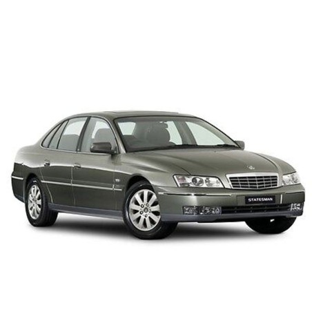
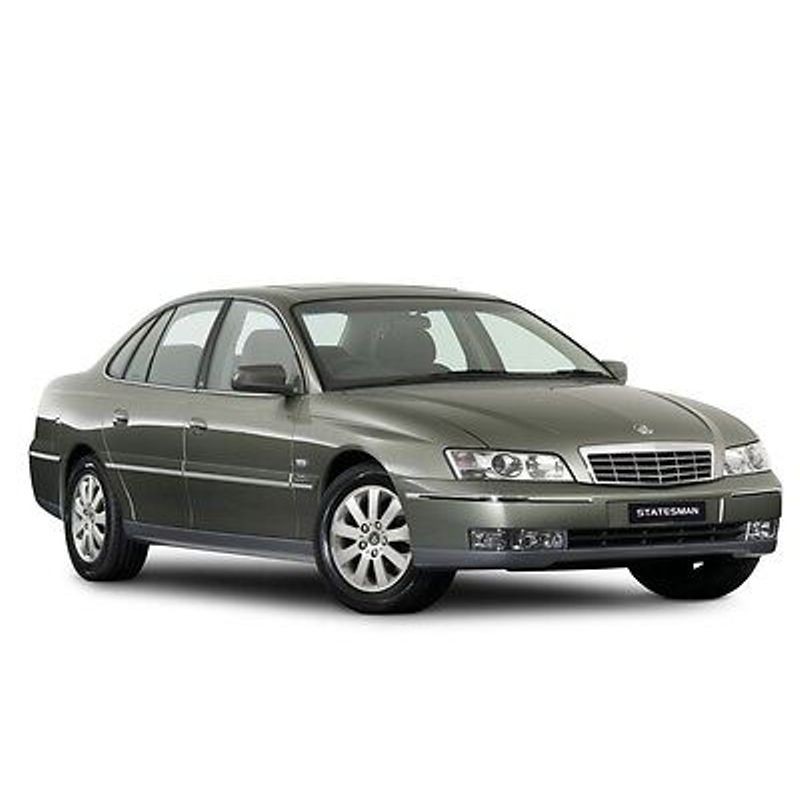
Holden WK Series (2003-2004) — Service & Repair Manual with Wiring Diagrams
This download contains service procedures and separately indexed electrical wiring/schematic information for Holden WK Series (2003-2004). The original technical index is retained below; indexed system names do not imply unlisted procedures.
Documentation language(s): English.
Original document details
- English Service Manual and Wiring Diagrams,-cars Holden WK Series (2003-2004)
Selected indexed topics: Section 0B Lubrication and Service; WIRING DIAGRAMS; V6 ENGINE.
Original technical index
- INTRODUCTION AND TECH 2
- - Section 00 Cautions and Notes
- - Section 0A General Information
- - Section 0B Lubrication and Service
- - Section 0C TECH 2
- EXTERNAL FITTINGS
- - Section 1A1 Body
- - Section 1A2 Body Dimensions
- - Section 1A4 Hood, Rear Compartment Lid, Liftgate & Endgate
- - Section 1A5 Front & Rear Door Assemblies
- - Section 1A6 Stationary Windows
- - Section 1A9 Exterior Ornamentation
- - Section 1B Sheetmetal
- - Section 1C Radiator Grille
- - Section 1D Bumper Bars
- - Section 1F2 Sunroof
- INTERNAL FITTINGS
- - Section 1A3 Instrument Panel and Console
- - Section 1A7 Seat Assemblies
- - Section 1A7A Seat Assemblies (Build No L253068 Onwards)
- - Section 1A8 Headlining and Interior Trim
- - Section 1E Cockpit Module
- HEATING AND AIR-CONDITIONING
- - Section 2A HVAC Climate Control (Manual A/C) – Description and Operation
- - Section 2B HVAC Climate Control (Manual A/C) – Removal and Installation
- - Section 2C HVAC Climate Control (Manual A/C) – Servicing and Diagnosis
- - Section 2D HVAC Occupant Climate Control (Auto A/C) – Description and Operation
- - Section 2E HVAC Occupant Climate Control (Auto A/C) – Removal and Installation
- - Section 2F HVAC Occupant Climate Control (Auto A/C) – Diagnostics
- SUSPENSION, STEERING, WHEELS, TYRES AND BRAKES
- - Section 3 Front Suspension
- - Section 4A Rear Suspension
- - Section 5A Service and Park Braking Systems
- - Section 5B ABS & ABS/TCS
- - Section 9 Steering
- - Section 10 Wheels and Tyres
- V6 ENGINE
- - Section 6A1 Engine Mechanical
- - Section 6B1 Engine Cooling
- - Section 6C1 Powertrain Management
- - Section 6D1-1A Charging System (100 Amp)
- - Section 6D1-1B Charging System (120 Amp)
- - Section 6E1 Emission Control
- - Section 6F1 Engine Tune
- V6 SUPERCHARGED ENGINE
- - Section 6A2 Engine Mechanical
- - Section 6B2 Engine Cooling
- - Section 6C2 Powertrain Management
- - Section 6D2-1 Charging System
- - Section 6E2 Emission Control
- - Section 6F2 Engine Tune
- V8 GEN III ENGINE
- - Section 6A3 Engine Mechanical
- - Section 6B3 Engine Cooling
- - Section 6C3 Powertrain Management
- - Section 6D3-1 Charging System
- - Section 6D3-2 Starting System
- - Section 6E3 Emission Control
- - Section 6F3 Engine Tune
- TRANSMISSION AND DRIVE TRAIN
- - Section 4B Final Drive and Drive Shafts
- - Section 4C Propeller Shaft and Universal Joints
- - Section 7C Hydra-Matic 4L60-E Automatic Transmission
- FUEL AND EXHAUST SYSTEMS
- - Section 8A1 Fuel Tank
- - Section 8A2 LPG System
- - Section 8B Exhaust System
- ELECTRICAL SYSTEMS
- - Section 12A Battery and Cables
- - Section 12B Lighting System
- - Section 12C Instruments
- - Section 12D Entertainment System
- - Section 12E Cruise Control
- - Section 12F Reverse Parking Aid
- - Section 12G Cellular Phone
- - Section 12H Rear-View Mirrors
- - Section 12I Multi Function Display
- - Section 12J Body Control Module
- - Section 12K Telematics
- - Section 12L Navigation System
- - Section 12M Occupant Protection System
- - Section 12N Washers, Wipers and Horn
- - Section 12O Fuses, Relays and Wiring Harnesses
- WIRING DIAGRAMS
- - Section 12P Wiring Diagrams