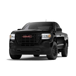
Complete electrical wiring diagrams for the 2014, 2015, 2016, 2017, 2018, 2019, 2020, and 2021 GMC Savana 2500.
Engine & Powertrain Systems
- Engine Performance circuits covering a wide range of powertrain options across the generation: 2.8L (VIN 1), 4.3L (VIN P), 4.8L (VIN A and VIN F), 6.0L (VIN B and VIN G), and 6.6L (VIN L).
- Starting and charging system diagrams specific to each engine configuration.
- Cooling fan electrical circuits.
- Transmission controls and shift interlock wiring.
Power & Data Distribution
- Power distribution and ground distribution networks.
- Computer data lines and vehicle communication networks.
- Body Control Modules (BCM) wiring.
Chassis & Brakes
- Anti-Lock Brakes (ABS) electrical circuits.
Safety & Security Systems
- Supplemental Restraints (airbags) and vehicle warning systems.
- Anti-Theft system electrical circuits.
- Cruise control wiring.
Comfort, Convenience & Body Electrical
- Air conditioning and defogger circuits.
- Instrument cluster, horn, and wiper/washer electrical circuits.
- Wiring for power seats, power windows, power mirrors, and power door locks.
- Trunk, tailgate, and fuel door release wiring.
Lighting Systems
- Headlights and complete exterior lighting circuits.
- Interior lighting schematics.
Infotainment & Navigation
- Radio and audio system wiring.
- Navigation system electrical circuits.
Engineering Breakdown: The Savana Electrical Backbone
Modern full-size vans like the GMC Savana are no longer simple mechanical workhorses; they are rolling networks of interconnected modules. From 2014-2021, the electrical architecture of this model evolved to support a massive range of powertrains, including the 2.8L Duramax turbo-diesel, the EcoTec3 4.3L V6, and the heavy-duty 6.6L L8T V8.
During troubleshooting, technicians often encounter "ghost" faults caused by high-resistance ground points or compromised harness routing. This workshop reference clarifies the relationship between the Body Control Modules (BCM) and peripheral sensors, allowing for a structured approach to voltage drop analysis. Understanding the signal flow from the ECU to the fuel pump driver or the instrument cluster is the difference between an afternoon repair and a week-long diagnostic headache.
Technical System Coverage by Model Year
This 849-page resource is meticulously indexed to cover the specific electronic variances across the 2014-2021 production run:
- Powertrain Performance: Complete schematics for every engine configuration, including the specialized CNG/LPG 6.0L LC8 and the high-output 6.6L LGH Duramax.
- Safety & Stability: Precise diagrams for Anti-Lock Brakes (ABS), Supplemental Restraints (SRS), and Warning Systems.
- Infrastructure: Comprehensive Power Distribution and Ground Distribution maps to identify every fuse box layout and splice point.
- Comfort & Utility: Circuitry for Air Conditioning, Power Seats, Navigation, and the specialized Shift Interlock systems.
- Exterior/Interior Lighting: Headlights, horn, and interior illumination schematics, including the often-complex Body Control Module interfaces.
Practical Diagnostic Use Cases
In real-world repair scenarios, having a visual map of the terminal locations and wire colors is indispensable. Consider these applications:
- Open/Short Circuit Tracing: Rapidly identify which connector pinout is responsible for an intermittent sensor signal.
- Voltage Drop Testing: Use the ground distribution diagrams to find the exact frame-to-engine ground strap location preventing proper starter engagement.
- Harness Integrity: Follow the harness routing to check for common rub-through points in the heavy-duty chassis.
- CAN-bus Communication: Analyze the computer data lines to determine why an ECU is failing to communicate with the diagnostic tool.
Why Accurate Data Matters in Modern Workshops
Inaccurate wiring information is a liability. Consequently, relying on generic "one-size-fits-all" diagrams for a vehicle with as many engine variations as the Savana leads to blown fuses and fried control units. For this reason, professional-grade diagrams are essential for protecting the vehicle's sensitive electronics. This technical document allows you to verify terminal locations and splice points before applying a probe, significantly reducing the risk of accidental short circuits during testing.
Workshop-Ready Technical Features
- Searchable PDF Format: Use keywords to jump directly to specific systems like "Cruise Control" or "Duramax Diesel."
- High-Detail Schematics: Zoom in on complex connector views without losing resolution, ensuring wire colors are easily identifiable.
- Universal Compatibility: Access the 168 MB file on any diagnostic tablet, smartphone, or workshop PC.
- Language: Technical English for maximum clarity in signal naming conventions.
Transaction, Access, and Delivery Details
We ensure that your workshop downtime is minimized through a streamlined delivery process:
- Accepted Payments: We process transactions via Credit Card, PayPal, Google Pay, and Apple Pay.
- Fulfillment: A secure download link is dispatched to your email address immediately after purchase. The PDF is also available for retrieval within your customer account download area.
- Access Terms: Your purchase is valid for 10 days or 10 individual downloads, providing ample time to back up the 849-page file to your primary devices.
- Assurance: We offer a delivery guarantee; if the automated system fails, a Dropbox backup link will be provided.
How-to Guide: For visual assistance on accessing your files, please view our Video Tutorial: How to Download.
Frequently Asked Questions
Is the 6.6L Duramax diesel circuitry covered for both the LGH and the newer L8T engines?
Yes. This comprehensive reference includes specific diagrams for the varying diesel configurations found across the 2014-2021 timeframe, ensuring you have the correct pinouts for both the engine performance and the starting/charging systems.
Can I use this manual to troubleshoot a "No Communication" error with the BCM?
Absolutely. The "Computer Data Lines" section provides the high-speed and low-speed CAN-bus maps required to verify continuity and resistance across the network, which is the standard procedure for resolving module communication failures.
Are the diagrams clear enough to read wire colors on a small tablet screen?
The PDF is rendered in high resolution with vector-based lines, meaning you can zoom in significantly on terminal locations and wire color codes without the image becoming pixelated, making it ideal for mobile diagnostic use.
Does this document include the fuse box layouts for the Flex-fuel 4.8L and 6.0L models?
Yes, the "Power Distribution" section details the internal fuse and relay assignments for all Vortec V8 variations, including the Flex-fuel and CNG/LPG models.
Access the full PDF guide now and eliminate guesswork in your repairs.