Service Manual Index
Power Distribution, Charging & Starting Architecture
- Charging system schematics, generator output circuits, and battery management loops.
- Starting system architecture covering engine switches, control relays, and starter motor wiring circuits.
Engine Management & Electronic Control Systems
- Comprehensive Engine Control Module (ECM) integration, accelerator pedal position sensors, and electronic throttle body control loops.
- Precision sensor networks including air-fuel ratio sensors, mass air flow (MAF) meters, engine coolant temperature sensors, and heated oxygen sensors.
- Crankshaft and camshaft position sensing circuits, knock sensors, and bank-specific variable valve timing controls (camshaft oil control valves for intake and exhaust sides across Bank 1 and Bank 2).
- Ignition system architecture detailing ignition coils, spark plugs, and sequential multiport fuel injection (SFI) system loops (segmented by canister pump module variants).
Fuel Delivery & Emission Control Networks
- Dual fuel delivery schematics featuring fuel filters, direct injection high-pressure injectors, port injection injectors, fuel main valves, and high-pressure/standard fuel pressure sensors.
- Fuel pump control circuits, high- and low-pressure fuel pumps, fuel pump ECUs, sender gauge assemblies, and fuel tank wiring configurations.
- Emission control loops covering evaporative emission canisters, purge valves, PCV valves, fuel tank caps, and system monitoring lines.
Intake & Exhaust Systems
- Exhaust management circuits detailing exhaust manifolds and exhaust pipe assemblies.
- Intake system architecture covering intake manifolds and airflow routing components.
Cooling & Lubrication Systems
- Cooling system loops managing radiators, thermostat assemblies, cooling fan ECUs, cooling fan motors, and primary water pumps.
- Lubrication system schematics tracking engine oil coolers, oil level sensors, oil pressure switches, and internal oil pumps.
Engine Mechanical Components
- Mechanical assembly references covering engine units, complete engine assemblies, cylinder blocks, cylinder heads, and cylinder head gaskets.
- Valve train and rotating assembly components including camshafts, drive belts, and front/rear crankshaft oil seals.
Mechanical Integrity and Workshop Risks
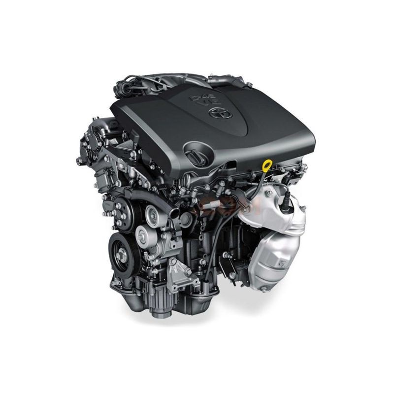
Performing a full teardown on a high-compression V6 without precise factory data is a gamble most professionals cannot afford. In real-world repair scenarios, even a minor tolerance deviation in a Cylinder Head Gasket seating or an improperly calibrated Camshaft Oil Control Valve can lead to immediate performance loss or long-term structural damage. Modern engines like the Toyota 2GR-FKS engine operate under extreme thermal and mechanical loads; consequently, the margin for error is virtually zero.
For this reason, relying on this workshop guide is vital for maintaining the engine's lifecycle. Improperly applied tightening sequences on the cylinder head or drivetrain components often result in microscopic warpage, leading to chronic leaks or oil consumption issues. By utilizing this resource, you ensure that every lubrication point and fastener meets the intended engineering load, effectively preventing the root causes of premature system failure.
Comprehensive Engineering Overview
This technical workshop reference offers an exhaustive mapping of the 2GR-FKS mechanical architecture. It covers the following systems in high detail:
- Engine Core Mechanics: Complete assembly and disassembly of the Cylinder Block, Cylinder Head, and Camshaft assemblies. Includes precise data for Front and Rear Crankshaft Oil Seals.
- D-4S Dual Injection System: Granular servicing of the Fuel Injector (Direct and Port Injection), Fuel Pressure Sensor (High Pressure), and high-pressure Fuel Pump ECU logic.
- VVT-iW Control: Detailed mapping of the Camshaft Oil Control Solenoids and valves for both intake and exhaust sides of Bank 1 and Bank 2.
- Thermal Management: Full procedures for the Water Pump, Thermostat, and the Cooling Fan ECU and motor network.
- Induction and Flow: Maintenance of the Intake Manifold, Exhaust Manifold, and the complete Intake System to preserve volumetric efficiency.
- Lubrication Circuits: Schematics for the Oil Pump, Engine Oil Cooler, and Oil Level Sensor to prevent high-friction wear patterns.
Practical Diagnostic and Repair Scenarios
During troubleshooting, the ability to zoom into high-fidelity technical diagrams makes the difference between a fast fix and a lost day. For example, diagnosing an intermittent rough idle might initially suggest a throttle body issue, but this service manual directs the technician to test the Mass Air Flow Meter and Air Fuel Ratio Sensor using specific resistance values.
As a result, you avoid the "parts cannon" approach to repair. In turn, when performing an Engine Unit replacement, the manual provides the necessary assembly procedures for the Drive Belt, Ignition System, and Starter to ensure the vehicle returns to the road in factory condition. Each procedure is designed to maximize time efficiency while guaranteeing the mechanical integrity of the drivetrain components.
Reliability Through Accurate Procedures
The interaction between the ECM and components like the Knock Sensor or Accelerator Pedal requires deep technical insight to troubleshoot effectively. Improper torque application on a Knock Sensor can actually change its frequency sensitivity, leading to phantom timing retard and reduced fuel economy. This resource provides the exact foot-pounds required to maintain sensor accuracy.
Furthermore, the Lubrication System section details how to verify Oil Pressure Switch operation, a critical step in diagnosing a flickering oil light before an expensive Oil Pump is condemned. In professional repair environments, these practical insights translate directly into cost savings and enhanced shop reputation.
Digital Manual Technical Features
This 92 MB repair manual PDF is engineered for the modern shop floor environment:
- High-Resolution Diagrams: Zoom in on intricate SFI system schematics without losing pixel clarity.
- Full Search Functionality: Instantly locate torque specifications or tightening sequences using keyword search.
- Cross-Device Compatibility: Access the 3,243 pages on your workshop tablet, smartphone, or laptop.
- Navigation Logic: Digitally indexed to jump between Emission Control (including the PCV Valve and Purge Valve) and the Starting System in seconds.
Payment and Instant Delivery
We prioritize immediate shop floor access. Your download is processed through a secure system:
- Payment Methods: Credit Card, PayPal, Google Pay, Apple Pay.
- Delivery: Secure download link sent to your email + customer account download immediately.
- Conditions: Link remains valid for 10 days or a total of 10 downloads.
- Guarantee: We provide backup delivery via Dropbox if needed to ensure you get your file.
- Video Tutorial: How to Download: Download Guide Video
Get immediate access to the full service manual and start diagnosing with precision.
Frequently Asked Questions
Does this manual cover the VVT-iW wide-angle camshaft system?
Yes. This Toyota 2GR-FKS Workshop Manual contains specific diagnostic and repair data for the advanced Camshaft Oil Control Valves for both Bank 1 and Bank 2, including the exhaust and intake side solenoids.
Are direct and port injection procedures separate?
Absolutely. The technical document provides distinct testing and replacement instructions for the Fuel Injector (Direct Injection) and Fuel Injector (Port Injection), ensuring you can troubleshoot the D-4S system accurately.
How precise are the torque sequences for the cylinder head?
The manual provides the exact multi-stage tightening sequences and angle-torque specifications required for the Cylinder Head and Cylinder Head Gasket to prevent thermal warpage.
Can this manual identify issues with the high-pressure fuel pump?
Correct. It includes service procedures for the Fuel Pump (For High Pressure), the Fuel Pressure Sensor, and the associated Fuel Main Valve, allowing for precise fuel system diagnostics.