- -$10.00
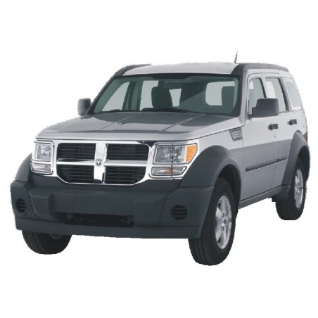


Ensure precise electrical diagnostics and repairs on your SUV with the comprehensive factory electrical wiring diagrams and components locator index for the Dodge Nitro (2007–2011). This 369-page, 28 MB professional reference provides detailed schematics, pinout data, and physical component mapping across all model trims and powertrain configurations.
Comprehensive component mapping covering underhood layouts, interior modules, and body harnesses across 39 specific zones:
A customer complains their windshield wipers won't turn off, the horn sounds randomly, and the door locks are completely dead. Most technicians immediately suspect the Totally Integrated Power Module (TIPM) has suffered internal water damage. In practical diagnostics, quoting a customer for a costly smart fuse box replacement without checking the communication network first can lead to a completely wasted repair bill.
This factory reference allows you to prove the module is bad by back-probing the specific inputs. The schematics contain a comprehensive 2-part Body Control Module breakdown and a dedicated 2-part Computer Data Lines map. By analyzing the sensor input traveling along the CAN bus, you can verify if the BCM is correctly sending the wake-up signal to the TIPM, or if a chafed wire resting against the subframe is pulling the whole network to ground.
Under the hood, the wiring architecture shifts drastically depending on whether the vehicle is equipped with the standard 3.7L V6 or the high-output 4.0L V6 found in the R/T and Detonator trims. Troubleshooting a lean code, an O2 sensor heater circuit failure, or an intermittent misfire requires understanding exactly how the Powertrain Control Module routes its 5-volt reference signals.
For this reason, the electrical schematics map out the engine performance circuits completely independently. You gain access to a massive 5-page spread specifically for the 3.7L engine and a distinct 4-page layout for the 4.0L powerplant. Instead of guessing which pin controls the coil packs or injectors, you can monitor the exact sensor input and watch the subsequent ECU response logic. Furthermore, the transmission shift interlock circuits are explicitly separated between the NAG1 (5-speed) and RLE (4-speed) gearboxes, eliminating confusion when diagnosing a vehicle stuck in park.
A corroded ground terminal can mimic dozens of different mechanical failures on this mid-size crossover. A severe drop in voltage at the primary engine ground might trigger a false electronic throttle warning or shut down the Anti-lock Brakes Circuit entirely.
Instead of tearing up the interior carpeting looking for a hidden splice pack, this workshop reference includes an extensive 39-point Electrical Components Locator. It visually guides you to the exact physical location of the module or ground point, whether it is hidden inside the "Left 'B' & 'C' Pillars," bolted to the "Left Side Of Dash," or tucked securely beneath the Totally Integrated Power Module itself. Knowing exactly where to place your multimeter leads saves hours of frustrating interior teardown.
When a stall is occupied by a no-crank vehicle, waiting days for technical literature to arrive in the mail is simply bad for business. Our digital deployment system ensures you receive the crucial data within seconds of a cleared transaction. We support rapid, encrypted checkout using Apple Pay, Google Pay, PayPal, and all standard credit cards.
What is the best way to trace a Dodge Nitro parasitic draw keeping the battery dead every morning?
Start by analyzing the 3-part Power Distribution Circuit alongside the Premium Radio and Hands-Free Module wiring diagrams. The schematics clearly dictate which circuits provide constant battery voltage to the infotainment system and external amplifiers. This allows you to perform a localized voltage drop test across the fuses without accidentally waking up the rest of the CAN network by opening a door.
I'm working on a 4.0L R/T model that refuses to shift out of park. Will this show the interlock mechanism?
Absolutely. The document explicitly separates the Shift Interlock Circuit between the standard RLE transmission and the NAG1 transmission used with the larger engine. You will see the exact brake switch inputs, CAN-bus signals, and solenoid grounds required to release the shifter assembly.
Does the component locator show the exact position of the TIPM connectors?
Yes. The Totally Integrated Power Module is referenced multiple times in the component locator section (specifically views 29, 35, and 39). It illustrates the physical orientation of the module and the routing paths of the main wiring harnesses leading out toward the engine compartment and dashboard bulkheads.
Are the navigation and audio amplifier circuits detailed for the premium sound packages?
Yes, the electrical diagrams include specific routing for the Navigation Circuit, DVD Player Circuit, and the 2-part Premium Radio Circuit. You can quickly trace the speaker outputs and remote turn-on leads to verify if an amplifier has blown an internal channel.