- -$10.00


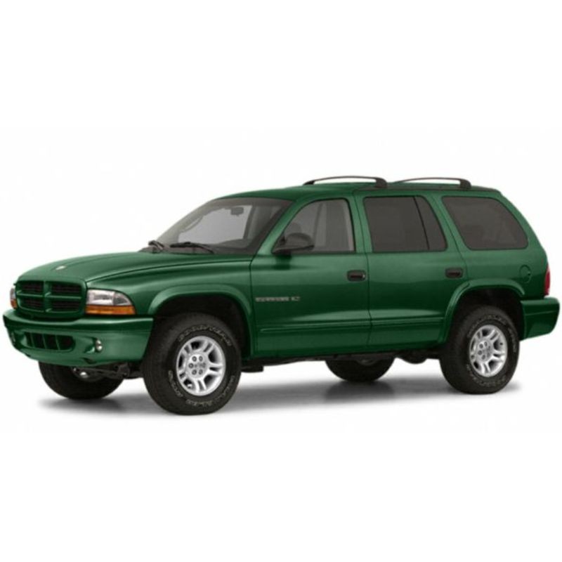
Ensure precise electrical troubleshooting and harness repair on classic SUVs with the comprehensive electrical wiring diagrams index for the Dodge Durango (1998–2003). This professional digital reference provides detailed schematics, pinout data, and physical component mapping across all model years and powertrain configurations.
Dedicated engine performance schematics categorized by available powerplants:
Cooling fan circuits, cruise control circuits, starting circuits, and charging system schematics.
Comprehensive component mapping covering underhood layouts, interior modules, and drivetrain harnesses across 7 specific reference zones:
Tackling a crank-no-start condition on a 1999 5.9L Magnum often traps technicians who immediately assume a failed fuel pump. Without mapping the Auto Shutdown (ASD) relay loop or verifying the anti-theft immobilizer circuit, you are basically flying blind. In practical diagnostics, the electrical architecture of this mid-size SUV requires exact factory tolerances to navigate safely.
This technical resource maps out every single circuit from 1998 through 2003, providing the specific component locators—like identifying junctions on the left side of the dash versus the right side of the engine compartment—to keep your diagnostic process strictly linear.
One of the most frequent electrical failures on this platform revolves around the Central Timer Module. By the 2000 model year, Dodge split the system into Base and Premium CTM variations. When a Durango rolls in with erratic power door locks, a courtesy lamp that refuses to time out, or a battery that dies overnight, the CTM is usually involved.
Instead of arbitrarily snipping wires or bypassing interior lighting circuits, utilizing these schematics allows you to back-probe the exact connector. You can perform a precise voltage drop test across the anti-theft and central timer lines to see if the module itself is internally shorted or if a downstream door switch is simply holding the ground open.
The engine management strategies shifted significantly during this vehicle's production run. A technician looking at a 1998 5.2L engine performance circuit will find a completely different logic flow compared to a 2002 4.7L equipped with the Next Generation Controller (NGC).
During troubleshooting, assuming the transmission control circuits are identical across these years is a costly mistake. The 2002–2003 sections of this document detail the integrated NGC A/T circuits, outlining precisely how the transfer case module communicates with the primary network. If you lose 4WD engagement, this reference isolates whether the fault lies in the selector switch output or a broken physical wire near the left side of the transmission housing.
A classic workshop scenario: a customer complains that the instrument cluster flickers violently whenever the A/C blower motor ramps up. Less experienced hands might tear into the HVAC control head. However, experienced techs know that tracing the Ground Distribution Circuits (covered extensively in sections 22-26 depending on the year) often reveals a heavily corroded shared ground stud on the firewall.
Having the explicit ground splicing layout means you can map out exactly which systems share an earth point. A quick continuity check validates the circuit path, saving hours of unnecessary dashboard disassembly.
We know that when a vehicle is occupying a lift, waiting for data isn't an option. Securing this file is engineered for immediate shop deployment.
Get immediate access to the full service manual and start diagnosing with precision right now.
My 2002 4.7L keeps dropping into limp mode. Will this help trace the transmission control lines?
Yes. The 2002 section specifically separates the standard 4.7L A/T circuits from the 4.7L A/T NGC (Next Generation Controller) variations, giving you the exact pinouts needed to check for broken wires or resistance issues between the module and the valve body.
Are the ground distribution splice locations mapped out for both the early 5.2L and later 5.9L Magnums?
Absolutely. Each model year section dedicates multi-page diagrams specifically to Ground Distribution (e.g., Ground Distribution Circuit 1 of 2 and 2 of 2), which trace the grounding paths for all engine variants, including the specific blocks and chassis studs.
How deep does the interior electrical coverage go regarding the overhead console?
The reference includes dedicated schematics for the Overhead Console Circuit, the Automatic Day/Night Mirror, and the Premium Sound Radio Circuits, allowing you to trace power feed and data line interactions seamlessly across the roof harness.
If my diagnostic laptop requires a factory reset next week, am I locked out of the diagrams I bought?
No. Your purchase grants you 10 distinct downloads over a 10-day period. Even outside that window, our backup Dropbox guarantee ensures that you never lose access to your purchased diagnostic tools.