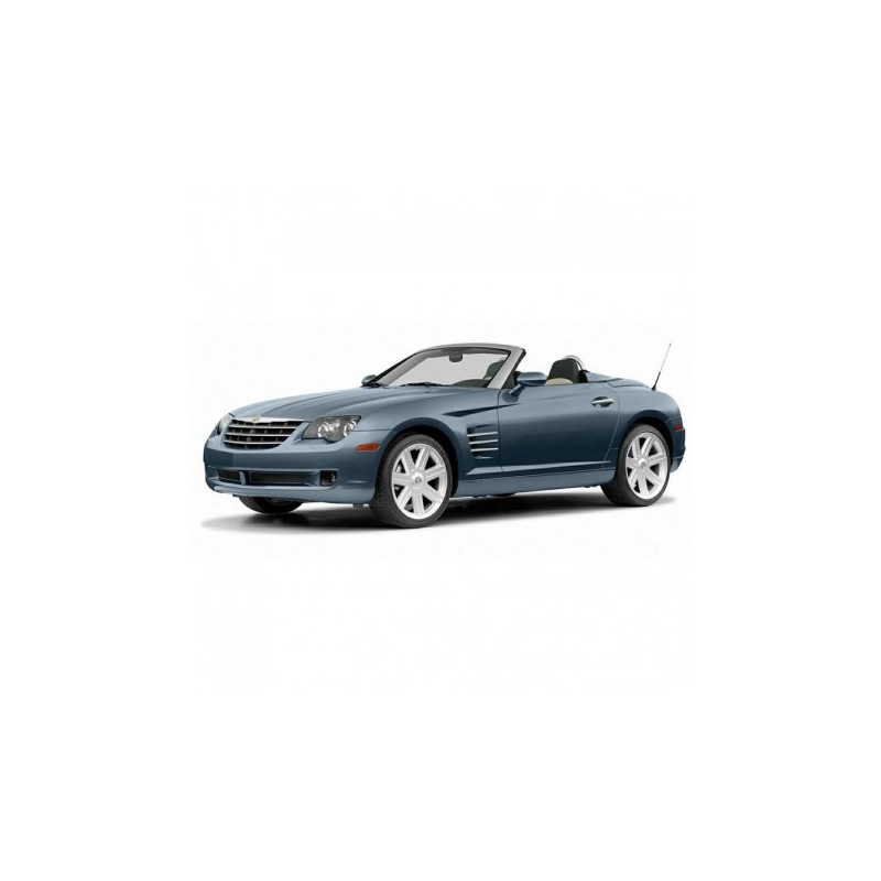
- -$10.00



A vehicle that cranks but immediately dies, followed by a locked dashboard, is a notoriously common sight with this platform. Usually, technicians start throwing parts at the ignition system. However, in practical diagnostics, the root cause is almost always a loss of handshake between the Body Control Module and the SKREEM module over the Computer Data Lines Circuit.
Because this chassis heavily utilizes early-2000s European multiplexing disguised under a Chrysler badge, testing the Anti-theft Circuit requires extreme precision. This technical document provides the explicit pinouts to verify voltage drops and ground paths between the immobilizer, the BCM, and the powertrain modules, preventing you from needlessly replacing an expensive ECU.
Unique to this sports car is the retractable rear spoiler, governed by the Active Bodyworks Circuit. When the spoiler fails to retract at low speeds or manually deploy via the center console switch, the failure point could be anywhere from a bad limit switch, a speed-sensor data interruption, or a corroded ground.
By following the exact routing laid out in these schematics, you can bypass the switch logic entirely to manually power the spoiler motor, instantly isolating the fault between a mechanical bind and an electrical open. Additionally, for the Roadster models, the Power Top/Sunroof Circuit diagrams are fully detailed (spanning multiple pages starting in 2005), allowing you to trace the complex microswitch logic that tells the hydraulic pump it is safe to operate.
Under the hood, the engine management wiring is tightly packed and sensitive to heat degradation. Naturally, the standard 3.2L naturally aspirated V6 demands a different testing approach compared to the supercharged SRT-6 variant.
To address this, the Engine Performance Circuits are broken down into three-page spreads per engine type. Crucially, the 2005 and 2006 sections distinctly map out the 3.2L SC architecture, detailing the specific bypass valve controls, intercooler pump wiring, and specialized Cooling Fan Circuit parameters required to keep the AMG-derived powerplant alive.
Finding a specific relay or splice on a hybrid platform like this can eat up half your labor time. Rather than tearing out the entire interior to find a module, you can rely on the extensive Electrical Components Locator.
This section completely eliminates the guesswork by providing 25 detailed geographic maps of the vehicle. Need to probe the convertible top controller? The locator points you directly to the Right Side Of Trunk or the Front Header. Looking for a specific inline connector for the Instrument Cluster Circuit? It maps out the exact harness routing behind the Left Kick Panel and the Center Console, meaning you only remove the trim panels you actually need to.
Time is your most valuable tool on the floor, so we don't make you wait for physical delivery. Checkout is instantly processed via Credit Card, PayPal, Apple Pay, or Google Pay. The moment payment clears, a secure download link for the full 274-page PDF is immediately emailed to you and permanently saved in your customer account. Your link remains active for 10 downloads or 10 days, giving you plenty of time to save it to your shop tough-book or tablet. If your local network drops the connection mid-download, we back up every purchase with a manual Dropbox link upon request. Never used our digital vault before? Watch our quick walkthrough right here: https://servicemanuals.info/How-to-Download.mp4. Pull the full EWD manual now and stop chasing phantom voltage drops.
Why won't my retractable spoiler go down, and how do I test it?
The spoiler is controlled by the Active Bodyworks Circuit, which relies on vehicle speed data and mechanical limit switches. Using the schematics provided, you can probe the central console switch connector for continuity, or supply direct 12v power to the motor pins listed in the diagram to determine if the motor is burned out or if the control module is denying the retract command.
Are the supercharged SRT-6 wiring diagrams included in this file?
Yes. The 2005 and 2006 sections explicitly separate the 3.2L SC, Engine Performance Circuit from the naturally aspirated 3.2L V6. You'll find the exact pinouts for the specialized supercharger cooling pump and unique powertrain control logic.
Where can I find the grounding points for the taillights and backup lamps?
The rear wiring harness grounds are clearly documented in the Ground Distribution Circuit schematics, while the exact physical locations (often located behind the trunk liner) are visually mapped out in the Electrical Components Locator under the Trunk and Rear Window/Trunk (Coupe) sections.
Does this document cover the specialized tire pressure system?
Absolutely. The manual includes dedicated diagrams for the Tire Pressure Monitoring Circuit, allowing you to trace the antenna receiver lines directly back to the main control module when a dash light won't clear despite all sensors having fresh batteries.