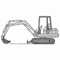
Bobcat Crawler Excavator ZX75 ZX125 Series - Service Repair Manual - Owners
Digital technical documentation with sections on ZX75 22990683 SM 10-06, FOREWORD, SAFETY INSTRUCTIONS. Review the complete contents below for the systems and procedures covered.
Manual contents
- ZX75 22990683 SM 10-06
- - CONTENTS
- - FOREWORD
- - SAFETY INSTRUCTIONS
- - Fire Prevention
- - SERIAL NUMBER LOCATIONS
- - Excavator Serial Number
- - Engine Serial Number
- - DELIVERY REPORT
- - INGERSOLL RAND EXCAVATOR IDENTIFICATION
- - MAINTENANCE SAFETY
- - SPECIFICATIONS
- - HYDRAULIC EXCAVATOR SPECIFICATIONS
- - Machine Dimensions
- - Performance
- - Controls
- - Engine
- - Electrical
- - Hydraulic System
- - Hydraulic System
- - Hydraulic Cycle Times
- - Swing System
- - Hydraulic Cylinders
- - Drive System
- - Brakes
- - Undercarriage
- - Track
- - Capacities
- - Digging Force
- - EXCAVATOR BOLT TORQUE
- - Specifications
- - TORQUE SPECIFICATIONS FOR BOLTS
- - Torque For General SAE Bolts
- - Torque For General Metric Bolts
- - HYDRAULIC FLUID SPECIFICATIONS
- - Specifications
- - FUEL, COOLANT AND LUBRICANTS
- - Chart
- - CONVERSIONS
- - Decimal And Millimeter Equivalents
- - U.S. To Metric Conversion
- - SAFETY AND MAINTENANCE
- - LIFTING AND BLOCKING THE EXCAVATOR
- - Procedure
- - LIFTING THE EXCAVATOR
- - Procedure
- - OPERATOR CAB
- - Description
- - Entering And Exiting The Excavator
- - Raising And Lowering The Left Console
- - Emergency Exit
- - TRANSPORTING THE EXCAVATOR
- - REAR COVER
- - Opening And Closing The Rear Cover
- - RIGHT SIDE COVER
- - Opening And Closing The Right Side Cover
- - SERVICE SCHEDULE
- - AIR CLEANER
- - Daily Check
- - Replacing The Filters
- - FRESH AIR FILTER
- - Removal And Installation
- - FRESH AIR FILTER
- - Removal And Installation
- - FUEL SYSTEM
- - Fuel Specifications
- - Filling The Fuel Tank
- - Pre-Filter Removal And Installation
- - Fuel Filter Removal And Installation
- - Draining The Fuel Tank
- - ENGINE LUBRICATION SYSTEM
- - Checking Engine Oil
- - Replacing Oil And Filter
- - HYDRAULIC SYSTEM
- - Checking And Adding Hydraulic Oil
- - Replacing The Hydraulic Oil
- - Hydraulic Filter Removal
- - Hydraulic Filter Installation
- - Hydraulic Filter Removal
- - Hydraulic Filter Installation
- - Hydraulic Filter Installation
- - Diagnostic Couplers
- - LUBRICATION OF THE EXCAVATOR
- - TRAVEL MOTOR
- - Checking Oil Level
- - Draining The Travel Motor
- - ALTERNATOR BELT
- - Adjusting Belt Tension
- - FAN/FUEL PUMP BELT
- - Adjusting Belt Tension
- - AIR CONDITIONING COMPRESSOR BELT
- - Adjusting Belt Tension
- - CAB TILT PROCEDURE
- - Installing The Cab Tilt Hinges
- - Tilting The Cab
- - HYDRAULIC SYSTEM
- - HYDRAULIC SYSTEM INFORMATION
- - Troubleshooting Chart
- - Description
- - BOOM CYLINDER
- - Testing
- - Removal And Installation
- - Parts Identification
- - Disassembly
- - Assembly
- - ARM CYLINDER
- - Testing
- - Removal And Installation
- - Parts Identification
- - Disassembly
- - Assembly
- - BOOM OFFSET CYLINDER
- - Testing
- - BOOM OFFSET CYLINDER
- - Removal And Installation
- - Parts Identification
- - Disassembly
- - Assembly
- - BUCKET CYLINDER
- - Testing
- - Removal And Installation
- - Parts Identification
- - Disassembly
- - Assembly
- - BLADE CYLINDER
- - Testing
- - Removal And Installation
- - Parts Identification
- - Disassembly
- - Assembly
- - RELIEF VALVES
- - Description
- - Testing The Three Spool Control Valve Main Relief Valve
- - Adjusting The Three Spool Control Valve Main Relief Valve
- - PORT RELIEF VALVES
- - Adjustment Procedure
- - PRESSURE REDUCING VALVE
- - Description
- - Testing
- - PRESSURE REDUCING VALVE
- - Adjustment
- - DUMP VALVE
- - Description
- - Testing
- - Adjustment
- - Removal And Installation
- - Parts Identification
- - Disassembly And Assembly
- - SIX SPOOL HYDRAULIC CONTROL VALVE
- - Removal And Installation
- - Control Valve Identification
- - Disassembly And Assembly
- - Left Travel And Right Travel Valve Section Disassembly And Assembly
- - Boom, Arm, Bucket And Auxiliary Valve Section Disassembly And Assembly
- - Inlet Valve Section Disassembly And Assembly
- - THREE SPOOL HYDRAULIC CONTROL VALVE
- - Removal And Installation
- - Parts Identification
- - Disassembly And Assembly
- - Boom Offset And Blade Valve Section Disassembly And Assembly
- - Inlet/Upperstructure Swing Valve Section Disassembly And Assembly
- - HYDRAULIC PISTON PUMP
- - Hydraulic Pump Work Sheet
- - HYDRAULIC PISTON PUMP
- - Testing Information
- - Pump Testing
- - Removal And Installation
- - Coupler Removal And Installation
- - Torque Limiter Valve Parts Identification
- - Torque Limiter Valve Removal and Installation
- - Torque Limiter Valve Disassembly
- - Torque Limiter Valve Assembly
- - Initial Torque Limiter Valve Setting
- - Pump Control Parts Identification
- - Pump Control Removal And Installation
- - Pump Control Disassembly And Assembly
- - Parts Identification
- - Disassembly
- - Assembly
- - HYDRAULIC GEAR PUMP
- - Removal And Installation
- - Parts Identification
- - Disassembly
- - Assembly
- - ACCUMULATOR
- - Description
- - Removal And Installation
- - TRAVEL MOTOR
- - Removal And Installation
- - Parts Identification
- - Disassembly
- - Assembly
- - SWIVEL JOINT
- - Removal And Installation
- - Parts Identification
- - Disassembly And Assembly
- - SWING MOTOR
- - Removal And Installation
- - Parts Identification
- - Disassembly
- - Assembly
- - SWING MOTOR DRIVE CARRIER
- - Removal And Installation
- - Parts Identification
- - Disassembly
- - Assembly
- - SWING BRAKE VALVE
- - Removal And Installation
- - Parts Identification
- - Disassembly And Assembly
- - SWING BRAKE RELEASE VALVE
- - Removal And Installation
- - Parts Identification
- - Disassembly And Assembly
- - JOYSTICK CONTROL PATTERN SELECTOR VALVE
- - Removal And Installation
- - Parts Identification
- - Disassembly And Assembly
- - JOYSTICK LOCKOUT/TWO SPEED VALVE
- - Removal And Installation
- - Parts Identification
- - Disassembly And Assembly
- - RIGHT CONTROL LEVER (JOYSTICK)
- - Testing
- - Handle Removal And Installation
- - Removal And Installation
- - Parts Identification
- - Disassembly And Assembly
- - LEFT CONTROL LEVER (JOYSTICK)
- - Testing
- - Handle Removal And Installation
- - Removal And Installation
- - Parts Identification
- - Disassembly and Assembly
- - TRAVEL LEVER/FOOT PEDAL VALVE
- - Left Travel Lever/Foot Pedal Valve Removal And Installation
- - Right Travel Lever/Foot Pedal Valve Removal And Installation
- - Parts Identification
- - Disassembly And Assembly
- - HYDRAULIC FILTER MOUNT
- - Removal And Installation
- - HYDRAULIC RESERVOIR
- - Removal And Installation
- - SECONDARY FRONT AUXILIARY VALVE
- - Removal And Installation
- - Parts Identification
- - Disassembly And Assembly
- - HYDRAULIC BREAKER APPLICATION VALVE
- - Removal And Installation
- - Parts Identification
- - Disassembly And Assembly
- - AUXILIARY HYDRAULIC FLOW CONTROL VALVE
- - Removal And Installation
- - Parts Identification
- - Disassembly And Assembly
- - AUXILIARY HYDRAULIC FLOW CONTROL/HYDRAULIC BREAKER APPLICATION VALVE
- - Removal And Installation
- - Parts Identification
- - Disassembly And Assembly
- - BLADE VALVE
- - Removal And Installation
- - Parts Identification
- - Disassembly And Assembly
- - BLADE FLOAT VALVE
- - Removal And Installation
- - Parts Identification
- - Disassembly And Assembly
- - BOOM OFFSET VALVE
- - Removal And Installation
- - Parts Identification
- - Disassembly And Assembly
- - BOOM LOAD HOLDING VALVE
- - Removal And Installation
- - Parts Identification
- - Disassembly
- - Assembly
- - OIL TEMPERATURE REGULATOR
- - Description
- - Removal And Installation
- - AUXILIARY HYDRAULICS SELECTOR VALVE
- - Removal And Installation
- - HYDRAULIC PISTON PUMP DRIVE COUPLER
- - Removal And Installation
- - UNDERCARRIAGE
- - BLADE
- - Removal And Installation
- - TRACKS
- - Track Lug Height
- - Rubber Track Clearance
- - Steel Track Clearance
- - Track Adjustment
- - Rubber Track Removal And Installation
- - TRACK FRAME
- - Disassembly And Assembly
- - Drive Sprocket Removal And Installation
- - TRACK IDLER
- - Parts Identification
- - Disassembly
- - Assembly
- - UPPER TRACK ROLLER
- - Parts Identification
- - Disassembly
- - Assembly
- - LOWER TRACK ROLLER
- - Parts Identification
- - Disassembly
- - Assembly
- - GREASE CYLINDER
- - Parts Identification
- - Disassembly
- - Assembly
- - TRACK DAMAGE IDENTIFICATION
- - Cutting Of Steel Cords
- - Abrasion Of Embedded Metals
- - Separation Of Embedded Metals
- - Separation Of Embedded Metals Due To Corrosion
- - Cuts On The Lug Side Rubber
- - Cracks On The Lug Side Rubber Due To Fatigue
- - Lug Abrasion
- - Cracks And Cuts On The Lug Side Rubber
- - Abrasion Of The Track Roller Side
- - Cuts On The Edges Of Track Roller Side
- - UPPERSTRUCTURE & SWING SECTION
- - UPPERSTRUCTURE
- - Removal And Installation
- - Swing Bearing Removal And Installation
- - CAB
- - Removal And Installation
- - Door Removal And Installation
- - Front Window Removal And Installation
- - Front Window Disassembly And Assembly
- - Front Window Gas Strut Removal And Installation
- - Front Window Pivot Frame Removal And Installation
- - Lower Front Widow Removal And Installation
- - Door, Left Side, Right Side And Rear Window Removal
- - Door, Left Side, Right Side And Rear Window Installation
- - Cab Visor Removal And Installation
- - Top Window Removal And Installation
- - SEAT AND SEAT MOUNT
- - Removal And Installation
- - RIGHT CONSOLE
- - Description
- - LEFT CONSOLE
- - Removal And Installation
- - Disassembly And Assembly
- - Console Lockout Switch Removal And Installation
- - ENGINE SPEED CONTROL
- - Removal And Installation
- - Disassembly And Assembly
- - CONTROL LEVERS
- - Description
- - FUEL TANK
- - Removal And Installation
- - HORN
- - Removal And Installation
- - SWING FRAME
- - Removal And Installation
- - Bushing Removal And Installation
- - FLOOR MAT
- - Removal And Installation
- - BOOM
- - Removal And Installation
- - ARM
- - Removal And Installation
- - BUCKET
- - Removal And Installation
- - REAR COVER
- - Removal And Installation
- - RIGHT SIDE COVER
- - Removal And Installation
- - COUNTERWEIGHT
- - Removal And Installation
- - ELECTRICAL SYSTEM AND ANALYSIS
- - ELECTRICAL SYSTEM INFORMATION
- - Troubleshooting Chart
- - Description
- - Fuse And Relay Location
- - BATTERY
- - Servicing
- - Removal And Installation
- - Using A Booster Battery (Jump Starting)
- - ALTERNATOR
- - Removal And Installation
- - Parts Identification
- - Alternator Identification
- - Charging System Check
- - STARTER
- - Removal And Installation (S/N 522311001 & Above)
- - Parts Identification (All Models)
- - FRONT CAB LIGHT
- - Removal And Installation
- - Disassembly And Assembly
- - TWO SPEED SWITCH
- - Removal And Installation
- - FUEL LEVEL SENDER
- - Removal And Installation
- - WIPER MOTOR
- - Removal And Installation
- - BATTERY DISCONNECT SWITCH
- - Removal And Installation
- - INSTRUMENT PANEL
- - Removal And Installation
- - E-Prom Information
- - ENGINE SERVICE
- - TROUBLESHOOTING
- - Chart
- - MUFFLER
- - Removal And Installation
- - AIR CLEANER
- - Removal And Installation
- - ENGINE
- - Removal And Installation
- - RADIATOR/OIL COOLER
- - Removal And Installation
- - Hydraulic Check Valve Removal And Installation
- - Hydraulic Check Valve Disassembly And Assembly
- - FLYWHEEL
- - Removal And Installation
- - Flywheel Ring Gear
- - HEATING, VENTILATION, AIR CONDITIONING
- - EVAPORATOR/HEATER UNIT
- - Removal And Installation
- - Disassembly And Assembly
- - HEATER/AC FAN
- - Removal And Installation
- - Resistor Removal And Installation
- - AIR CONDITIONING SYSTEM FLOW
- - Principles
- - Chart
- - COMPONENTS
- - Identification
- - SAFETY
- - Safety Equipment
- - REGULAR MAINTENANCE
- - Heater Air Filter
- - Air Conditioning Compressor Belt
- - Cleaning The Condenser
- - BASIC TROUBLESHOOTING
- - Poor A/C Performance
- - Compressor Drive Belt Inspection
- - Cleaning The A/C Evaporator Coil & Heater Coil
- - Cleaning The A/C Evaporator Coil & Heater Coil (S/N 528911001 & Above And 528611001 & Above)
- - Checking The Electrical System
- - Engine Coolant By-Passing The Heater Valve
- - GENERAL AIR CONDITIONING SERVICE GUIDELINES
- - Compressor Oil
- - Compressor Oil Check
- - Component Replacement And Refrigeration Leaks
- - SYSTEM TROUBLESHOOTING CHART
- - Blower Motor Does Not Operate
- - Gauge Pressure Related Troubleshooting
- - TEMPERATURE/PRESSURE
- - Chart
- - SYSTEM CHARGING AND RECLAMATION
- - Reclamation Procedure
- - COMPRESSOR
- - Removal And Installation
- - Compressor Clutch Disassembly And Assembly
- - CONDENSOR
- - Removal And Installation
- - RECEIVER/DRYER
- - Removal And Installation
- - PRESSURE SWITCH
- - Removal And Installation
- - AIR CONDITIONING SYSTEM
- - Evaporator Unit Removal And Installation
- - Disassembly And Assembly
- - Thermostat Removal And Installation
- - Evaporator Removal And Installation
- - Fan Removal And Installation
- - ALPHABETICAL INDEX
- ZX75-ZX125 22856462 SM 3-06
- - TABLE OF CONTENTS ZX75
- - TABLE OF CONTENTS ZX125
- - Load Excavator ZX75
- - Load Excavator ZX75
- - Diesel Engine
- - Electrical System
- - Transmission
- - Travel Range
- - Working Hydraulics
- - Pressure and Setting Values (Working)
- - Slew Drive
- - Lubricants
- - Maintenance Parts
- - Capacities
- - Hydraulic System
- - Electrical System
- - Power Supply
- - Horn
- - Check Module
- - Load Warning Sensor
- - Load Warning Device
- - Joystick, Right
- - Working Floodlights
- - Reach Limitation
- - Control Module
- - Charge Indicators
- - Oil Pressure Indicators
- - Air Filter Indicators
- - Hydraulic Oil Filter Indicators
- - Hydraulic Oil Level
- - Working Hydraulics
- - Breaker
- - Fast Travel
- - Float Position
- - Swing Brake
- - Additional Control Circuit I
- - Additional Control Circuit II
- - Inspection Plan
- - Operator Controls
- - Instrument Panel
- - Working Equipment Parallel-Tracks
- - Cabin Suspension
- - Instructions for Tilting the Cabin
- - Load Excavator ZX125
- - Load Excavator ZX125
- - Diesel Engine
- - Electrical System
- - Transmission
- - Travel Range
- - Working Hydraulics
- - Pressure and Setting Values (Travel)
- - Slew Drive
- - Lubricants
- - Maintenance Parts
- - Capacities
- - Hydraulic Installations
- - Setting Instructions
- - Function
- - Power Control Valve
- - Description of Function
- - Test and Pressure Setting
- - Rexroth Valve Bank SX 18
- - Start-Up
- - Brakes (Downhill)
- - Electrical System
- - Power Supply
- - Horn
- - Check Module
- - Hydraulic Oil Level
- - Load Warning Device
- - Working Hydraulics
- - Joystick, Left
- - Restriction of Reach
- - Working Floodlights
- - Check Module
- - Inspection Plan
- - Operator Controls
- - Instrument Panel
- ZX75 22509384 OM 8-04
- - TABLE OF CONTENTS
- - Introduction
- - General
- - Warranty
- - Notes on Using the Instruction Book
- - Environmental Requirements
- - Pictograms
- - Safety & Prevention of Accidents
- - Introductory Remarks
- - Proper Use
- - General Safety Notes
- - Operation
- - Danger Zone
- - Transport of Persons
- - Stability
- - Travel Operation
- - Operation
- - Guides
- - Danger of Falling Objects
- - Working in the Vicinity of Underground Power Lines
- - Working in the Vicinity of Overhead Power Lines
- - Operation in Closed Rooms
- - Work Stoppages
- - Crane Operations
- - Change of Work Attachments, Maintenance, Repair
- - Recovery, Loading & Transportation
- - Monitoring & Inspections
- - Fire Protection
- - Emergency Exit
- - Other Dangers
- - Technical Data
- - Diesel Engine
- - Electrical System
- - Crawler Unit
- - Steering
- - Brakes
- - Hydraulic System
- - Hydraulic Pumps
- - Lubricants
- - Filling Quantities
- - Fuel, Lubricant & Coolant Specifications
- - Alternative Recommendation for Other Temperature Ranges
- - Specific Ground Pressure
- - Sound Level Values, Vibration
- - Dimensions & Weights
- - Excavator Installation
- - Work Attachments
- - Optional Equipment
- - Operation
- - Operator Controls
- - Instrument Panel
- - Engine
- - Starting the Engine
- - Monitoring During Operation
- - Switching off the Engine
- - Driver's Seat
- - Heating/Ventilation/Air Conditioning
- - Heating
- - Ventilation
- - Air Conditioning (Option)
- - Front Window
- - Ventilation Position
- - Tracking and Steering
- - Tracking Forward or Reverse
- - Taking Bends
- - Spot - Turning
- - Turning Over One Crawler
- - Rubber Crawler Chains
- - Parking the Machine
- - Working Operation
- - General
- - Operation of Work Functions
- - Operation of Work Equipment
- - Operation - Articulation
- - Operation - Dozer Blade
- - Float Position
- - Operation - Additional Control Circuit
- - Rock Breaker Operations
- - Grab Operations, Swing Bucket, etc.
- - Changing Work Attachments
- - General
- - Assembly of Work Attachments
- - Procedure for Changing Work Attachments
- - Clamshell Grab
- - Changing Procedure
- - Hydraulic Rock Breaker
- - Attachment
- - Working with the Hydraulic Rock Breaker
- - Maintenance
- - Using the Machine for Load Hook Applications
- - Overload Warning Device
- - Using the Machine for Load Hook Applications
- - Possible Forms of Attachment, Attaching Loads
- - Attaching and Guiding Loads
- - Checking the Overload Warning Device
- - Work Equipment - Monobloc and Boom
- - Tiedown & Transport
- - Tiedown of the Machine
- - Loading the Machine by use of a Crane
- - Transport of the Machine
- - Care & Maintenance
- - General Notes
- - Intervals
- - Regular Oil Analysis
- - Advantages of an Oil Analysis
- - Oil Analysis Intervals
- - Warranty
- - Inspection Parts & Aids
- - Lubricants
- - Care & Cleaning
- - Notes for Winter Operation
- - Hydraulic Oil
- - Engine Oil
- - Coolant
- - Battery Charge
- - Fuel
- - Checking, Maintenance & Inspection Plans
- - Initial Inspection (Delivery/Handing-Over Inspection)
- - Daily and Weekly Tasks
- - Daily
- - Weekly
- - Overview of Lubricating Points
- - Inspection Plan
- - Inspection & Maintenance Work
- - Engine Oil
- - Checking the Engine Oil Level
- - Engine Oil Change
- - Engine Oil Filter
- - Engine Oil Cooling System/Hydraulic Oil Cooler
- - Fuel System
- - Fuel Level
- - Draining Water from the Fuel Filter
- - Fuel Filter
- - Fuel Tank
- - Air Filter, Air Intake
- - Dust Ejection Valve
- - Air Intake
- - Cartridge Maintenance Interval
- - Air Filter - Main Cartridge
- - Air Filter Safety Cartridge
- - Cartridge Replacement
- - Main Cartridge
- - Safety Cartridge
- - V-Belts
- - Checking the V-Belt Tension
- - Checking the V-Belt Tension without a Measuring Device
- - Tensioning V-Belts
- - Replacing V-Belts
- - Checking the Valve Lash
- - Checking & Adjusting
- - Hydraulic Oil Tank
- - Checking the Hydraulic Oil Level
- - Changing the Hydraulic Oil
- - Hydraulic Oil Return Filter
- - Cartridge Maintenance Interval
- - Breather of Hydraulic Oil Tank
- - Crawler Gear Units
- - Checking the Oil Level in the Crawler Gear Unit
- - Oil Change
- - Crawler Chains
- - Checking the Crawler Chain Tension
- - Rubber Crawler Chain
- - Steel Crawler Chain
- - Tensioning the Crawler Chain
- - Releasing the Crawler Chain Tension
- - Replacing Track Shoes
- - Replacement
- - Swing Gear
- - Swing Bearing
- - Lubrication of Toothing
- - Lubrication of Bearing Races
- - Checking the Fastening
- - Dust Filter for Cab Ventilation
- - Removal
- - Re-installation
- - Windshield Washer System
- - Electrical Equipment
- - Battery
- - Disconnecting the Battery
- - Installing the Battery
- - Lighting & Warning Equipment
- - Shutdown
- - Preservation (Temporary Shutdown)
- - During Shutdown
- - After Shutdown
- - Trouble-Shooting
- - General
- - Engine
- - Appendix
- - Immobilizer
- - Activating the system
- - The Immobilizer is Self-Activating
- - Deactivating the System
- - Operating Malfunctions
- - Possible Sources of Malfunction
- - Damaged or Lost Code Keys
- - Delivery & Handing-Over Instructions
- - Operating Instructions
- - Spare Parts List
- - Warranty
- - Maintenance & Inspection Plan
- ZX125 22509392 OM 8-04
- - TABLE OF CONTENTS
- - Introduction
- - General
- - Warranty
- - Notes on Using the Instruction Book
- - Environmental Requirements
- - Pictograms
- - Safety & Prevention of Accidents
- - Introductory Remarks
- - Proper Use
- - General Safety Notes
- - Operation
- - Danger Zone
- - Transport of Persons
- - Stability
- - Travel Operation
- - Operation
- - Guides
- - Danger of Falling Objects
- - Working in the Vicinity of Underground Power Lines
- - Working in the Vicinity of Overhead Power Lines
- - Operation in Closed Rooms
- - Work Stoppages
- - Crane Operations
- - Change of Work Attachments, Maintenance, Repair
- - Recovery, Loading & Transportation
- - Monitoring & Inspections
- - Fire Protection
- - Emergency Exit
- - Other Dangers
- - Failure of Hydraulic System
- - Technical Data
- - Engine
- - Electrical System
- - Travel Mechanism
- - Steering
- - Brakes
- - Hydraulic System
- - Lubricants
- - Filling Quantities
- - Fuel, Lubricant & Coolant Specifications
- - Alternative Recommendation for Other Temperature Ranges
- - Specific Ground Pressure
- - Sound Level Values & Vibration
- - Dimensions & Weights
- - Excavator Installation
- - Carrying Capacity
- - Work Attachments
- - Optional Equipment
- - Operation
- - Operator Controls
- - Instrument Panel
- - Description - Instrument Panel
- - Engine
- - Starting the Engine
- - Monitoring During Operation
- - Switching off the Engine
- - Driver's Seat
- - Heating / Ventilation / Air Conditioning
- - Heating
- - Ventilation
- - Air Conditioning
- - Front Window
- - Ventilation Position
- - Tracking & Steering
- - Tracking Forward or Reverse
- - Making Turns
- - Counter Rotation
- - Rubber Crawler Chains
- - Parking the Machine
- - Working Operation
- - General
- - Operation of Work Functions
- - Operation of Work Equipment
- - Operation - Articulation
- - Operation - Dozer Blade
- - Float Position
- - Operation - Additional Control Circuit
- - Additional Control Circuit I (25/17)
- - Rock Breaker Operations
- - Grapple Operations (Swing Bucket, etc.)
- - Additional Control Circuit Il (25/2)
- - Changing Work Attachments
- - General
- - Assembly of Work Attachments
- - Procedure for changing work attachments
- - Clamshell Grapple
- - Changing Procedure
- - Hydraulic Rock Breaker
- - Attachment
- - Working with the Hydraulic Rock Breaker
- AND MORE...