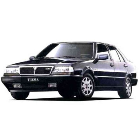


LANCIA THEMA 8.32 - ENGINE WORKSHOP, SERVICE, REPAIR MANUAL - WIRING DIAGRAMS
- English Engine Service Manual / Repair Manual and Wiring Diagrams, to vehicles Lancia Thema 8.32.
CONTENTS:
INTRODUCTION AND TECHNICAL DATA
Introduction
- car exterior features
- car interior features
- identification data and location on vehic1e
- weights - dimensions
- perfonnance - fuel consumption
- colours
- optional equipment
- capacities
- characteristics of lubricants
Technical data
Engine
- characteristics
- power curves
- cylinder blockjcrankcase, crankshaft and
Associated components
- cylinder head assembly and valve gear
Components
- lubrication
- cooling system - fuel system
Clutch
Gearbox and differential
Braking system
Steering
Wheels
Front suspension
Rear suspension
Electrical equipment
- starting
- recharging
- microplex electronic ignition
ENGINE
Removing-refitting power unit
- diagrammatic view of engine,
Parti al cross section
Dismantling at the bench
- order of operations
Cylinder block/crankcase -
Cylinder bores
- cylinder block/crankcase
- cylinder bores
Crankshaft and associa ted
Components
- crankshaft 29
- crankshaft bearings 31
- checking crankshaft bearings pre-ioading 31
- measuring bearing clearance 33 - thrust washers 34
- crankshaft front cover incorporating oil pump 36
- crankshaft rear cover 41
- connecting rod-piston assembly 42
- gudgeon pin s 43
- piston rings 44
- connecting rods 46
- diagram showing connecting rod-piston assembly
- big end bearings
- measuring bearing clearance
Cylinder heads
- dismantling and checks
- valves
- valve guides
- camshafts
- measuring camshaft bearing clearance
- tappets
- cylinder head tightening
Cooling system
- Water pump (coolant)
Fitiing various devices
- flywheel
. Lubrication
- engine oil pressure relief valve
Valve timing
- timing
- adjusting timing belt tension
- adjusting tappet clearance
Reassembl y at the bench
- checking alignment between damper pulley
And water pump control pulley 96
- diagram showing operation of engine lubrication
System
- diagram showing operation of cooling
System
Special tools
~tightening torques
Fuel system
- diagram showing air supply
- universal fault diagnosis device
"electronic analyzer model proi"
- warnings .
- bosch ke3-jetronic electronically controlled
Mechanical injection system
Components
- diagram for checking air supply
System for leaks
- diagram showing main components to be checked
- bosch ke3-jetronic injection system control
Unit terminal connections
Diagnostic diagrams
- checking earth on connection 18
- checking earth on connection 15
- checking control unit supply for ke3
Jetronic injection system (and idle servoregulator)
From protective relay and appropriate flise
- checking engine speed impulses coming
From microplex electronic control unit
- checking continuity of pressure servoregulator
Winding
- checking idle servo-regujator winding
Continuity and operation
- checking engine coolant temperature
Sensor resistance
- checking switch on butterfly valve (idle Contact)
- checking switch on butterfly valve (full Power)
- checking cold start injector coil winding
Continuity and dynamic operation
- checking load engagement signale (from the air conditioning- relay contacts)
- checking load engagement signal (from the air conditioning relay coi!)
- checking potentiometer resistance continuity (pins l and 3)
- checking potentiometer sliding contacts (pins l and 2)
- summary of information and tests
Ignition: diagnostic dia grams
- microplex electronic ignition system wiring diagram
- checking microplex electronic ignition
Control unit earth
- checking microplex electronic ignition
Control unit supply
- checking continuity of tdc sensor
- checking continuity of engine rpm sensor
- Checking tdc sensor gap and magnetic
Efficiency
- checking rpm sensor gap and magen tic
Efficiency
- checking power module on ignition coil
(13 a)
- checking power module on ignition coil
(13 b)
- checking continuity of circuit for advance
Correction, with butterfly closed
- wiring diagram key (for supply and ignition
Diagnostic diagrams)
- summary of information and tests
Fuel system: checks
- checking electric fuel pump and speedometer
Relay
'- Connecting remote control simulator to
Vehicle electrical system
- draining fuel system for possible service
Operations
- coid start injector fuel pressure seal
- operation of cold start injector
- electric fuel pump flow rate
- checking fuel system pressure (ps)
- checking fuel system pres sure (holding)
- checks 00 fuel distribution-meteriog device
Aod 00 air flow meter
- checking sliding of metering device piston
And air flow meter levers
- checking movement of fuel metering device
Piston vacuum levers
- checking axial position of floating plate and
Controllevers
- checking contact position
- checking radial centering of floating plate
- checking injector opening pressure and jet
Configuration.
- checking injectors for fuelleaks
- checking injector flow rates for comparison
- cheekiog servo-regulator adjustmeot pressure
And eurreot
- checking rest current and relative adjustment
Pressure (pr)
- checking enrichment during starting,
After starting and during engine
Warming up stage
- checking enrichment during acceleration
- checking enrichment in full load conditions
- checking maximum rpm restriction
- checking fuel distribution-metering device
- checking operation of idle servo-regulator
- adjusting butterfly valves during idling
- adjusting idle mixture metering device (co) during idling
- fuel system fault diagnosis
Fuel sytem: operation
- bosch ke3-jetronic electronically controljed
Mechanical injection system
- fuel supply cireuit
- electric fuel pump
- pressure accumulator
- fuel filter
- fue! Pressure regulator
- pressure servo-regu!ator (electro-magnetic)
- fuel distribution-metering device
- injectors
- coid start injector
- engine coolant temperature sensor
- ke3-jetronic injection system control unit
- air supply cireuit
- air flow meter
- butterfly casings
- idle speed servo-regulator
ELECTRICAL EQUIPMENT