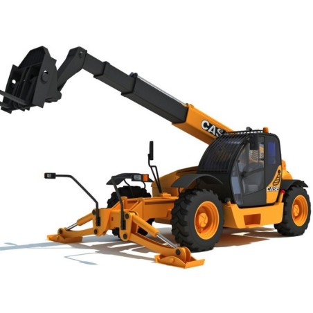


CASE TX130-40, TX130-43, TX130-45, TX140-43, TX140-45, TX170-45, TURBO - SERVICE MANUAL - MANUALE DI OFFICINA - MANUEL DE REPARATION - REPARATURANLEITUNG - MANUAL DE TALLER
- English, Italian, French, Spanish and German Service Manual, in PDF format, to telehandler Case TX130-40, TX130-43, TX130-45, TX140-43, TX140-45, TX170-45, Turbo.
CONTENTS:
TX130--40 turbo/TX130--43 turbo/TX130--45 turbo
TX140--43 turbo/TX140--45 turbo
TX170--45 turbo
TELESCOPIC HANDLERS
GENERAL LIST OF CONTENTS
SECTION 00 -- GENERAL
- General instructions . 1
- Safety rules 3
- Product identification . 6
- Environmental considerations . 9
- Maintenance techniques. 10
SECTION 10 -- ENGINE
- Description Page
- Coding of engines of origin 3
- Main engine specifications . 4
- General engine specifications 5
- Generalities . 7
- Description of engine main mechanical components . 13
- Lubrication 24
- Cooling . 29
- Mechanical injection fuel system. 31
- Injection assembly . 33
- Removal of the engine transmission group from the vehicle 43
- Engine overhaul on bench 46
- Replacement of injectors98
- Valve clearance 100
- Timing setting101
- Timing of injection pump . 102
- Electrical components. 103
- Troubleshooting 104
- Tooling 108
- Mounting plays . 112
SECTION 21 -- POWERSHIFT GEARBOX
- Description Page
- Gearbox assembly 5
- Idler gear case assembly7
- Gearbox operation . 8
- Transmission and Hydraulic oil circuit diagrams . 15
- Modulation valve operation 31
- Torque converter and heat exchanger hydraulic oil circuit 34
- Troubleshooting procedures . 37
- Pressure testing clutch and high pressure circuit 38
- Pressure testing torque converter and cooler circuit. 39
- Check points . 40
- Assembly instructions . 42
- Overhaul 45
- Special tools 104
SECTION 25 -- FRONT AXLE
- Description Page
- Specifications . 1
- Description . 2
- Operation 3
- Troubleshooting. 4
- Wheel toe--in check 5
- Component overhaul . 5
- Front axle removal procedure . 6
- Front axle overhaul 7
- Axle drive pinion bearing adjustment 52
- How to install and adjust the axle drive pinion 54
- Front drive shaft57
SECTION 27 -- REAR AXLE
- Description Page
- Specifications . 1
- Description . 2
- Operation diagram 3
- Component overhaul . 5
- Rear axle removal procedure . 5
- Overhaul . 6
- Special tools 7
SECTION 33 -- BRAKES
- Description Page
- Power brakes . 2
- Parking brake 3
- Brake disc adjustment . 6
- Troubleshooting. 7
- Brake disc replacement 8
SECTION 35 -- HYDRAULIC SYSTEM
- Description Page
- Technical data 2
- Description and operation3
- Steering system hydraulic circuit 3
- Steering valve 4
- Telescopic boom hydraulic circuit 6
- Component operation . 11
- Hydraulic pump11
- Hydraulic scheme 11
- Delivery side divider valve . 11
- Pressure reducing valve. 13
- Front loader controls 15
- Power steering (OSPQ). 19
- Telescopic boom distributor 21
- Auxiliary controls distributor 24
- Cylinders 25
- Arms. 35
- Boom removal. 35
- Working platform . 43
- Procedure for the calibration of the personnel carrier platform electronic controller . 47
- Special tools . 53
SECTION 55 -- ELECTRICAL SYSTEM
- Description Page
- Chapter 1 – Electrical system general
- Electrical equipment specifications. 1
- Electrical system and fuse2
- Controls and instruments. 6
- Use of the tip--over prevention system . 16
- Bulb replacement . 23
- Protecting the electrical systems during charging or welding 26
- Starting the machine using jump leads 27
- Temporary wiring repair. 28
- Electrical system general fault finding . 30
- Working platform . 31
- Special tools . 46
- Chapter 2 – Circuit diagrams
- List of connectors 48
- List of components . 49
- How to use the circuit diagrams 50
- Diagram 1: Starting/Recharge/Warning lights/Indicator 51
- Diagram 2: Transmission55
- Diagram 3: Wheel alignment/Hydraulic solenoids/Brake system . 57
- Diagram 4: Arm control 59
- Diagram 5: Stabiliser 61
- Diagram 6: Lights/Windscreen wiper 63
- Diagram 7: Work lamps/Roof beacon light. 65
- Diagram 8: Tilting prevention system/Roof wiper 67
- Diagram 9: Sound system heating/Electric socket/Roof lamp. 69
- Diagram 10: Air conditioner 71
- Chapter 3 -- Wiring list
- Instrument panel wiring. 75
- Cab wiring . 81
- Front wiring 82
- Rear wiring 83
- Engine wiring 85