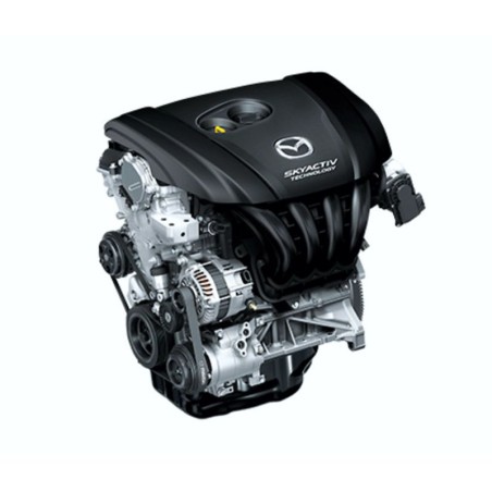


MAZDA SKYACTIV-G 2.0 (2015) ENGINE - WORKSHOP, SERVICE, REPAIR MANUAL
- English Service Manual / Repair Manual, for Mazda Skyactiv-G 2.0 (2015) Engine.
CONTENTS:
GENERAL INFORMATION
- How To Use This Manual . 00-00–2
- Range Of Topics00-00–2
- Service Procedure 00-00–2
- Symbols 00-00–4
- Advisory Messages00-00–4
- Units 00-00–5
- Conversion From Si Units
- (Système International D'unités) . 00-00–5
- Number Of Digits For
- Converted Values 00-00–5
- Converted Value Rounding Off And
- Rounding Up/Down. 00-00–5
- Abbreviations . 00-00–6
- Fundamental Procedures . 00-00–6
- Preparation Of Tools And Measuring
- Equipment . 00-00–6
- Special Service Tools00-00–6
- Disassembly . 00-00–6
- Inspection During Removal,
- Disassembly 00-00–7
- Arrangement Of Parts00-00–7
- Cleaning Of Parts . 00-00–7
- Reassembly . 00-00–8
- Adjustment00-00–8
- Rubber Parts And Tubing. 00-00–8
- Torque Formulas . 00-00–9
- Vise. 00-00–9
ENGINE MECHANICAL
- Electric variable valve timing
- Motor/driver inspection. 01-10–2
- Hydraulic variable valve timing
- Actuator inspection. 01-10–3
- Electric variable valve timing
- Actuator inspection. 01-10–3
- Oil control valve (ocv)
- Inspection . 01-10–4
- Coil resistance inspection01-10–4
- Spool valve operation inspection . 01-10–4
- Hydraulic lash adjuster (hla)
- Inspection . 01-10–5
- Rocker arm inspection 01-10–5
- Engine overhaul
- Service warning. 01-10–5
- Engine
- Mounting/dismounting . 01-10–5
- Mounting 01-10–5
- Dismounting . 01-10–6
- Timing chain disassembly01-10–7
- Water pump pulley
- Disassembly note 01-10–9
- Crankshaft pulley lock bolt
- Disassembly note 01-10–10
- Oil pan disassembly note . 01-10–10
- Engine front cover
- Disassembly note 01-10–10
- Front oil seal disassembly note . 01-10–11
- Chain tensioner removal note . 01-10–11
- Oil pump driven sprocket
- Disassembly note 01-10–12
- Cylinder head
- Disassembly (i) . 01-10–13
- Electric variable valve timing actuator,
- Hydraulic variable valve timing
- Actuator disassembly note. 01-10–15
- Camshaft cap disassembly note . 01-10–15
- Rocker arm disassembly note. 01-10–15
- Hla disassembly note . 01-10–15
- Cylinder head disassembly note . 01-10–15
- Cylinder head
- Disassembly (ii) . 01-10–16
- Valve keeper disassembly note01-10–17
- Valve seal disassembly note 01-10–17
- Cylinder block
- Disassembly (i) . 01-10–18
- Flywheel (mtx), drive plate (atx)
- Disassembly note 01-10–19
- Rear oil seal removal note 01-10–19
- Cylinder block
- Disassembly (ii) 01-10–20
- Pilot bearing disassembly note 01-10–21
- Connecting rod cap
- Disassembly note. 01-10–21
- Connecting rod bearing
- Disassembly note. 01-10–21
- Piston, connecting rod
- Disassembly note. 01-10–21
- Snap ring disassembly note01-10–22
- Lower cylinder block
- Disassembly note. 01-10–22
- Thrust bearing and main bearing
- Disassembly note. 01-10–23
- Crankshaft disassembly note. 01-10–23
- Cylinder head inspection . 01-10–23
- Valve seat
- Inspection/repair 01-10–24
- Valve, valve guide
- Inspection . 01-10–25
- Valve guide replacement. 01-10–26
- Removal 01-10–26
- Installation01-10–27
- Valve spring inspection 01-10–27
- Camshaft inspection. 01-10–28
- Cylinder block inspection . 01-10–30
- Oil jet valve inspection 01-10–30
- Piston inspection. 01-10–30
- Piston ring inspection01-10–31
- Piston pin inspection. 01-10–32
- Piston and connecting rod
- Inspection . 01-10–33
- Connecting rod inspection . 01-10–33
- Connecting rod clearance
- Inspection . 01-10–33
- Crankshaft inspection . 01-10–34
- Flywheel inspection01-10–35
- Pilot bearing inspection. 01-10–36
- Bolt inspection. 01-10–36
- Cylinder block assembly (i) 01-10–37
- Thrust bearing and main bearing
- Assembly note01-10–38
- Plate assembly note01-10–38
- Lower cylinder block
- Assembly note01-10–39
- Piston pin assembly note01-10–40
- Snap ring assembly note01-10–40
- Piston Ring Assembly Note 01-10–41
- Connecting Rod Bearing
- Assembly Note01-10–41
- Piston, Connecting Rod
- Assembly Note01-10–41
- Connecting Rod Cap
- Assembly Note01-10–42
- Pilot Bearing Assembly Note 01-10–42
- Cylinder Block Assembly (Ii) 01-10–43
- Oil Baffle Plate Assembly Note. 01-10–44
- Oil Pump Assembly Note. 01-10–44
- Water Pump Assembly Note . 01-10–45
- Rear Oil Seal Assembly Note 01-10–46
- End Plate Assembly Note. 01-10–47
- Flywheel (Mtx), Drive Plate (Atx)
- Assembly Note01-10–48
- Cylinder Head Assembly (I)01-10–48
- Valve Seal Assembly Note01-10–49
- Valve Spring Assembly Note. 01-10–49
- Valve Keeper Assembly Note 01-10–49
- Water Outlet Assembly Note. 01-10–50
- Thermostat Assembly Note 01-10–50
- Cylinder Head Assembly (Ii) 01-10–51
- Cylinder Head Assembly Note. 01-10–53
- Water Inlet Pipe Assembly Note 01-10–54
- Hla Assembly Note. 01-10–55
- Rocker Arm Assembly Note . 01-10–55
- Camshaft Assembly Note . 01-10–56
- Electric Variable Valve Timing Actuator,
- Hydraulic Variable Valve Timing
- Actuator Assembly Note . 01-10–58
- Timing Chain Assembly01-10–59
- Oil Pump Driven Sprocket
- Assembly Note01-10–61
- Timing Chain Assembly Note01-10–62
- Engine Front Cover
- Assembly Note01-10–64
- Oil Pan Assembly Note 01-10–68
- Electric Variable Valve Timing
- Motor/Driver Assembly Note. 01-10–69
- Front Oil Seal Assembly Note. 01-10–70
- Crankshaft Pulley Lock Bolt
- Assembly Note01-10–71
- Water Pump Pulley
- Assembly Note01-10–72
- Oil Shower Pipe Installation Note. 01-10–73
- Cylinder Head Cover
- Installation note . 01-10–73
TECHNICAL DATA
- Technical Data . Td-2
- Engine technical dataTd-2
SPECIAL TOOLS
- Special Tools .st-2
- Engine sst .st-2