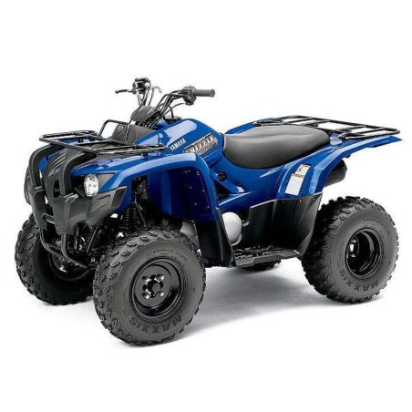


YAMAHA GRIZZLY 300 - WORKSHOP, SERVICE, REPAIR MANUAL - WIRING DIAGRAMS
- English Service Manual / Repair Manual and Wiring Diagrams, for ATV Yamaha Grizzly 300.
CONTENTS:
00 FRONT PAGE
- Table Of Contents
01 GENERAL INFORMATION
- 01 01 Machine Identification
- 01 02 Important Information
- 01 03 Special Tools
02 SPECIFICATIONS
- 02 01 General Specifications
- 02 02 Engine Specifications
- 02 03 Chassis Specifications
- 02 04 Electrical Specifications
- 02 05 Tightening Torques
- 02 06 How To Use The Conversiontable
- 02 07 General Tightening Torquespecifications
- 02 08 Lubrication Points And Lubricant Types
- 02 09 Coolant Flow Diagrams
- 02 10 Oil Flow Diagrams
- 02 11 Cable Routing
03 PERIODIC CHECKS AND ADJUSTMENTS
- 03 01 Introduction
- 03 02 Periodic Maintenance Chart For The Emission Controlsystem
- 03 03 General Maintenance And Lubrication Chart
- 03 04 Seat, Fenders And Fuel Tank
- 03 05 Engine
- 03 06 Chassis
- 03 07 Electrical System
04 ENGINE
- 04 01 Engine Removal
- 04 02 Cylinder Head
- 04 03 Rocker Arms And Camshaft
- 04 04 Valves And Valve Springs
- 04 05 Cylinder And Piston
- 04 06 C.D.I. Magneto
- 04 07 Belt Drive
- 04 08 Starter Clutch
- 04 09 Oil Pump
- 04 10 Crankcase And Crankshaft
- 04 11 Transmission
05 COOLING SYSTEM
- 05 01 Radiator
- 05 02 Thermostat
- 05 03 Water Pump
06 CARBURETOR
- 06 01 Carburetor
07 DRIVE SHAFT
- 07 01 Rear Axle/Final Drive Gear And Drive Shaft
08 CHASSIS
- 08 01 Front And Rear Wheels
- 08 02 Front And Rear Brakes
- 08 03 Steering System
- 08 04 Front Arms And Front Shock Absorber Assemblies
- 08 05 Rear Shock Absorber And Swingarm
09 ELECTRICAL
- 09 01 Electrical Components
- 09 02 Checking Switch Continuity
- 09 03 Checking The Switches
- 09 04 Checking The Bulbs And Bulbsockets
- 09 05 Ignition System
- 09 06 Electric Starting System
- 09 07 Starter Motor
- 09 08 Charging System
- 09 09 Lighting System
- 09 10 Signal System
- 09 11 Cooling System
10 TROUBLESHOOTING
- 10 01 Starting Failure/Hard Starting
- 10 02 Poor Idle Speed Performance
- 10 03 Poor Medium And High-Speed Performance
- 10 04 Faulty Gear Shifting
- 10 05 Faulty Clutch
- 10 06 Overheating
- 10 07 Faulty Brake
- 10 08 Shock Absorber Malfunction
- 10 09 Unstable Handling
- 10 10 Lighting System
11 YFM30GB WIRING DIAGRAM
