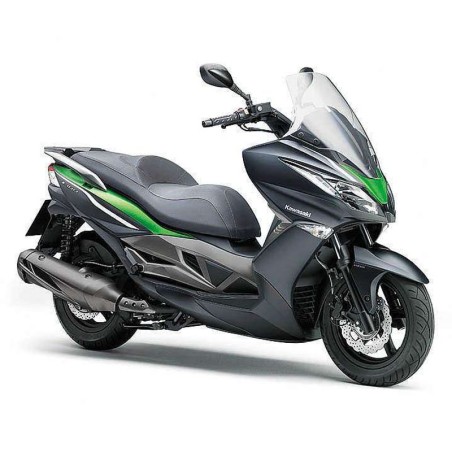


KAWASAKI J300 (2014-2015) - WORKSHOP, SERVICE, REPAIR MANUAL - WIRING DIAGRAMS
- English Service Manual and Wiring Diagrams, for motorcycles Kawasaki J300 (2014-2015).
CONTENTS:
GENERAL INFORMATION
- Before Servicing
- Model Identification
- General Specifications
- Unit Conversion Table
PERIODIC MAINTENANCE
- Periodic Maintenance Chart
- Torque and Locking Agent
- Specifications
- Special Tools
- Periodic Maintenance Procedures
FUEL SYSTEM (DFI)
- Exploded View
- DFI System
- DFI Parts Location
- Specifications
- Special Tools and Sealant
- DFI Servicing Precautions
- Troubleshooting the DFI System
- DFI System Troubleshooting Guide
- Self-Diagnosis
- Throttle Sensor Position and Idle Speed Control Valve Actuator Position Reset
- Throttle Sensor (Service Code 06)
- Intake Air Pressure Sensor (Service Code 09)
- Water Temperature Sensor (Service Code 12)
- Vehicle-down Sensor (Service Code 15)
- Oxygen Sensor - not activated (Service Code 17, Equipped Models)
- Fuel Injector (Service Code 33)
- Ignition Coil (Service Code 37)
- Fuel Pump Relay (Service Code 41)
- Radiator Fan Relay (Service Code 43)
- Oxygen Sensor Heater (Service Code 45)
- Idle Speed Control Valve Actuator (Service Code 49)
- Crankshaft Sensor (Service Code 66)
- Yellow Engine Warning Indicator Light (LED)
- ECU
- DFI Power Source
- Fuel Line
- Fuel Pump
- Throttle Grip and Cables
- Throttle Body Assy
- Air Cleaner
- Fuel Tank
COOLING SYSTEM
- Exploded View
- Coolant Flow Chart
- Specifications
- Special Tools and Sealant
- Coolant
- Water Pump
- Radiator
- Thermostat
- Hoses and Pipes
- Water Temperature Sensor
ENGINE TOP END
- Exploded View
- Specifications
- Special Tools and Sealant
- Cylinder Head Cover
- Camshaft Chain Tensioner
- Camshaft
- Rocker Arm, Rocker Shaft
- Cylinder Head
- Valves
- Cylinder, Piston
- Intake Manifold
- Muffler
CONVERTER SYSTEM
- Exploded View
- Specifications
- Special Tools
- Left Crankcase Cover
- Drive Pulley
- Clutch/Driven Pulley
ENGINE LUBRICATION SYSTEM
- Exploded View
- Engine Oil Flow Chart
- Specifications
- Special Tool
- Engine Oil and Oil Filter
- Oil Pressure Relief Valve
- Oil Pump
- Oil Pipe
ENGINE REMOVAL/INSTALLATION
- Exploded View
- Engine Removal/Installation
CRANKCASE/CRANKSHAFT
- Exploded View
- Specifications
- Special Tools and Sealant
- Crankcase
- Crankshaft, Connecting Rod
- Starter Motor Clutch
WHEELS/TIRES
- Exploded View
- Specifications
- Special Tools
- Wheels (Rims)
- Tires
- Hub Bearing
FINAL DRIVE
- Exploded View
- Specifications
- Special Tools
- Final Gear Case
BRAKES
- Exploded View
- Specifications
- Special Tool
- Brake Lever, Brake Pedal
- Calipers
- Brake Pads
- Master Cylinder
- Brake Disc
- Brake Fluid
- Brake Hose
- Anti-Lock Brake System (Equipped Model)
SUSPENSION
- Exploded View
- Specifications
- Special Tools
- Front Fork
- Rear Shock Absorber
STEERING
- Exploded View
- Special Tools
- Steering
- Steering Stem
- Handlebar
FRAME
- Exploded View
- Seat
- Fairings
- Covers
- Fenders
- Frame
- Windshield
- Guard
- Center Stand, Side Stand
- Rear View Mirror
ELECTRICAL SYSTEM
- Exploded View
- Specifications
- Special Tools and Sealant
- Parts Location
- Wiring Diagram
- Wiring Diagram (ABS Equipped Model)
- Precautions
- Electrical Wiring
- Battery
- Charging System
- Ignition System
- Electric Starter System
- Lighting System
- Radiator Fan System
- Oil Pressure Warning System
- Meter, Gauge, Indicator Unit
- Switches and Sensors
- Fuse
APPENDIX
- Cable, Wire, and Hose Routing
- Troubleshooting Guide