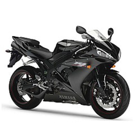


YAMAHA YZF-R1 (2004-2006) - WORKSHOP, SERVICE, REPAIR MANUAL - WIRING DIAGRAMS
- English Service Manual / Repair Manual and Wiring Diagrams, for motorcycles Yamaha YZF-R1 2004 to 2006.
CONTENTS:
HOW TO USE THIS MANUAL
TABLE OF CONTENTS
CHAPTER 1 GENERAL INFORMATION
- Motorcycle Identification
- Features
- Important Information
- Checking the Connections
- Special Tools
CHAPTER 2 SPECIFICATIONS
- General Specifications
- Engine Specifications
- Chassis Specifications
- Electrical Specifications
- Conversion Table
- General Tightening Torque Specifications
- Tightening Torques
- Lubrication Points and Lubricant Types
- Cooling System Diagrams
- Engine Oil Lubrication Chart
- Lubrication Diagrams
- Cable Routing
CHAPTER 3 PERIODIC CHECKS AND ADJUSTMENTS
- Introduction
- Periodic Maintenance Chart for the Emission Control System
- General Maintenance and Lubrication Chart
- Seats
- Fuel Tank
- Cowlings
- Air Filter Case
- Engine
- Chassis
- Electrical System
CHAPTER 4 CHASSIS
- Front Wheel and Brake Discs
- Rear Wheel and Brake Disc
- Front and Rear Brakes
- Front Fork
- Handlebars
- Steering Head
- Rear Shock Absorber Assembly
- Swingarm and Drive Chain
CHAPTER 5 ENGINE
- Engine
- Camshaft
- Cylinder Head
- Valves and Valve Springs
- Starter Clutch and Generator
- Crankshaft Position Sensor
- Clutch
- Shift Shaft
- Oil Pan and Oil Pump
- Crankcase
- Connecting Rods and Pistons
- Crankshaft
- Transmission
CHAPTER 6 COOLING SYSTEM
- Radiator
- Oil Cooler
- Thermostat
- Water Pump
CHAPTER 7 FUEL INJECTION SYSTEM
- Fuel Injection System
- Throttle Bodies
- Air Induction System
CHAPTER 8 ELECTRICAL SYSTEM
- Electrical Components
- Checking Switch Continuity
- Checking the Switches
- Checking the Bulbs and Bulb Sockets
- Ignition System
- Electric Starting System
- Starter Motor
- Charging System
- Lighting System
- Signaling System
- Cooling System
- Fuel Pump System
- Self-Diagnosis
CHAPTER 9 TROUBLESHOOTING
- Incorrect Engine Idling Speed
- Poor Medium-and-High-Speed Performance
- Faulty Gear Shiftiing
- Faulty Clutch
- Overheating
- Overcooling
- Poor Braking Performance
- Faulty Front Fork Legs
- Unstable Handling
- Faulty Lighting or Signaling System
WIRING DIAGRAM
